Because of the holidays, TI E2E™ design support forum responses will be delayed from Dec. 25 through Jan. 2. Thank you for your patience.

This thread has been locked.

If you have a related question, please click the "Ask a related question" button in the top right corner. The newly created question will be automatically linked to this question.

General purpose RF transceiver Solution?

Other Parts Discussed in Thread: CC2500, CC2510, CC2592, CC2590, SMARTRFTRXEBK, CC2500EMK, MSP430F5438A

 Hello,

I am having difficulty finding a general purpose RF transceiver.


In a nutshell, I am trying to find a general purpose RF transceiver chip which can communicate with an MCU via an SPI, UART or parallel port interface. Therefore I am looking for an RF chip that can send and receive data through radio frequency and can relay its information to an nearby MCU via the mentioned interface standards. Please refer to attachment.

The RF transceiver when paired with the MCU is defined as a unit. Eventually I am looking to adapt 2 or more units to form an RF mesh network where the units can communicate with themselves.


THE PROBLEM: 

I have looked into dev kits like:

CC2543-CC2544 Development Kit

and this is an overkill for me and doesn't fit into my actual design. The RF transceivers that I am looking for are without an embedded communication protocol. I've also looked into, zigbee, xbee, Digi, Synapse ect... and all come with a pre-loaded communications protocol which communicates to a central dongle which is connected to a computer. I see the beauty of such a setup since one can use the graphical interface to access every radio for addressing and MCU programming purposes. But my environment does not require such a convenience.

Therefore, the general purpose RF transceiver chip I am looking for will simply send and transmit data based on the instructions my MCU will provide to it. This means that the MCU that's connected to the RF transceiver will have its own communication protocol. Additionally, the MCU will receive its own commands from my proprietary system as shown in the attachment. 

REQUIREMENTS

If possible, the transceivers should work with a 2.4GHZ frequency band and allow for a minimal communication distance in open air of between 1000 and 2000 ft. In the future this distance may need to increase. A 250kbs RF data transfer rate or greater is fine. These radios may be installed in homes or commercial environments. For initial prototyping purposes we would need it to be in a PDIP package if at all possible. I will need the datasheets to the RF transceiver part along with the bill of materials and schematics for the PCB antenna dimensions and all the components that may be required for the part.

The RF transceiver chip should consist of minimal amounts of pin outs and a minimal required amount of external components. Therefore, pins for a chip enable, transmit enable, receive enable along with a few other pins for the coil and/or for the crystal attachment if necessary would be perfect. I've used RF "transmitters" (RX or TX)  in the passed in an 8 pin dip. This would be very useful for me if Texas instruments would have a "transceiver" (RX AND TX all in one chip) with this sort of simplicity.

Also if there are any development kits for this sort of simple transceiver, please provide links.

All help or feedback is greatly appreciated!

Thank you Texas Instruments for your help and your support!


Robert


  • Hello Robert,

    You can see a list of all TI 2.4GHz proprietary RF solutions on the product tab here:
    www.ti.com/.../products.page

    The CC2500 / CC2510 may be something to look at. You can find more detail, such as schematics, ref designs, etc., on each product by visiting the respective product folder.

    Best wishes
  • Hi JXS,

    One question thought, can the  CC2500 do 1000ft In open

    air? I tried looking for that in the data sheet and I couldn't

    find it!

    And correct me if I am wrong there are development kits

    that exist for the CC2500 right?

    I thank you very much for your help.... much appreciated !

    Robert

  • Hello,

    I am having difficulty finding a general purpose RF transceiver. I have spoken with TI support and they asked me to update my post/question with a complete list of my requirements. So I figure I will also simplify my initial post as well.

    In a nutshell, I am trying to find a general purpose RF transceiver chip which can communicate with an MCU via SPI or UART. Therefore I am looking for an RF chip that can send and receive data through radio frequency and can relay its information to a nearby MCU via SPI or UART. Please refer to attachment from original post up above.

    Therefore, the general purpose RF transceiver chip I am looking for will simply send and transmit data based on the data my MCU will provide to it. The MCU that's connected to the RF chip will also receive its own commands from my proprietary CPLD system as shown in the attachment.

    So for example, my MCU would enable a transmit pin on the RF chip and send a byte to the RF chip via SPI. Immediately after, the RF chip sends out the byte... that's it! As for reading info from the RF chip, my MCU would enable a receive pin on the RF chip and immediately, the RF chip sends out the last byte it received via SPI to the MCU. That's it!

    THEREFORE TO RECAP, I AM LOOKING FOR:

    1) A general purpose RF chip (which only does the RF data communications -RX/TX) and that can be configured via an external MCU through SPI or UART. (Meaning that this RF chip does not require a computer to set itself up or configured). All set ups and configurations for the RF chip will be done by the MCU.

    2) If the RF part described in point #1 doesn't exist at TI, then you can recommend an RF part with the capability of uploading an unlicensed proprietary embedded communications protocol in the RF chip, then that's fine too. (BUT BARE IN MIND, AGAIN, THE RF CHIP MUST BE ABLE TO BE CONFIGURED BY AN MCU). We don't mind pre-loading a protocol in the RF chips, but all RF-chip setups must be done by the MCU via SPI.

    3) An RF communication range of 1000 to 2000 feet. (Open air) -Around 1000ft is good too

    4) The RF frequency band could be 2.4GHZ or 900MHZ. (Preferably 2.4GHZ)

    5) 250Kbs is an acceptable communication rate.

    6) A development kit for the RF chips with examples in C code that illustrates how the MCU in the dev kit configures the RF chip's registers in order to allow an RF communication between two(2) RF dev boards.

    7) AND FINALLY, IF AND I MEAN ONLY "IF", TI has an RF chip with an embedded controller (all in one) with a communication rate of 250kbs AND can go up to 1200 feet AND is 2.4GHZ (or 900MHZ) AND can be configured without the use of a computer (as described above), then this could also be a possibility.

    8) Assure the RF chips are suitable to be used in homes or commercial establishments like restaurants or warehouses.

    9) The design should allow for the antenna to be drawn on the RF chip's PC board. Therefore a PC board antenna is required for the RF modules.

    All other possible recommendations are welcome.
    All help or feedback is greatly appreciated!

    Thank you Texas Instruments for your help and your support!

    Robert
  • Hello Robert,

    We do not specify range in our data sheets since range is demonstrated based on a number of device and environmental factors. We have a pinned post "Excel sheet to estimate range for Indoor and Outdoor" at the top of the forum to help you estimate your range in your operating configuration and conditions.

    For dev kits, you can find this on the "Tools and Software" tab of the CC2500 (or any) product folder: www.ti.com/.../toolssoftware
    You can also use a CC2590/CC2592 range extender in your design if required.

    For Sub-1GHz transceivers and wireless MCUs, you can find the overview page on the same tree as the previous link:
    www.ti.com/.../overview.page

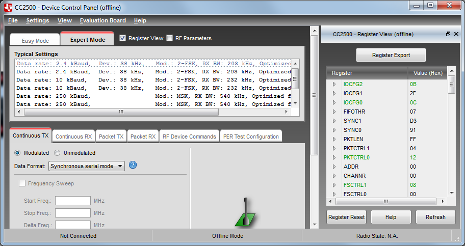
    You can also use SmartRF Studio 7 to test your radio configuration and generate the register settings which can be used in your code.

    I hope these options allow you to select the right device for your design.

    Best wishes
  • Hello JSX,

    Thank you for your reply.

    I didn't know It was possible to incorporate an extra

    chip  that can act as a range extender.... that's good to know.

    So if I understand you, the CC2500 isn't a chip that can be ccessed through SmartRF studio software  but we can use  SmartRF studio figure out the chip's register values based on the features we choose in the SmartRF studio software and then copy those into our MCU code to program the CC2500.  Right?

    Also, if there is one thing standing between deciding weather to seriously dwelve in or not with the CC2500 is that I would  really like to be sure about point #9  in my last post. Space is a concern and would like to make sure I can actually integrate a PC board antenna as opposed to using a pencil antenna.

    Also, one last thing, forgive me for asking so many questions as this is one of my first attempts to try and understand IT's  development boards. For the CC2500 there are 6 to choose from:

    -CC2500EMK

    -Boost - CCEMADAPTER

    -EZ430-RF2500T

    -Ez430-RF2500-SEH

    -EZ430-RF25

    -SMARTRFTRXEBK

    And then there is the Evaluation Module (EM) Adapter.

    So at this point I'm not sure exactly which one I need to buy .... I suppose I need two small boards with the antennas (which are the CC2500) and two bigger dev boards that hold the MCU.

    Can you please provide me the correct links to the dev boards I need to buy so I can get up and running. This would eliminate any errors on my behalf .

    Thank you so much for your help.

    Robert

  • Hi Robert,

    You are correct. To evaluate CC2500, you will need a SMARTRFTRXEBK and CC2500EMK. This setup supports SmartRF Studio. Note that the CC2500EMK kit has two CC2500 evaluation modules but the SMARTRFTRXEBK is a single evaluation board, so two SMARTRFTRXEBKs would be required.

    Once you have done the evaluation you can fly-wire the SMARTRFTRXEBK + CC2500EMK to your MCU via the exposed pins or use the Boost - CCEMADAPTER to mount the CC2500 EM to a compatible TI MCU LaunchPad dev board, such as MSP430.

    Best wishes
  • Hello Robert,

    SMARTRFTRXEBK + CC2500EMK can be used with SmartRF Studio.

    #9
    Small PCB antennas work well in the 2.4 GHz band. Refer to these links for more info about our antenna solutions:
    www.ti.com/.../swra351a.pdf
    processors.wiki.ti.com/.../Antenna
  • Hi JXS,

    Thank you for responding.

    ---[OPTION A]---
    So, ok you propose that I buy the SMARTRFTRXEBK kit two times and I buy the CC2500EMK kit one time. So do you mean I need two computers to test an RF link where each SMARTRFTRXEBK kit connects to a different computer ? Or can I just use one computer and use one USB port to connect to one (1) SMARTRFTRXEBK kit and another USB port to connect to the other SMARTRFTRXEBK kit ?

    =========================================================================================================

    ---[OPTION B]---
    Also I am a little confused, yesterday, I spent over an hour on the phone with a TI support agent and we came up with a different solution where he suggested that the EZ430-RF2500 kit was the right kit for me to evaluate the CC2500 wireless chip.

    The EZ430-RF2500 kit seems to propose that we have one CC2500 (wireless target board) hooked up to the eZ430-RF USB debugging interface board (which connects to a computer) and the other CC2500 (wireless target board) is hooked up to the battery expansion board. Furthermore, he explained that I can access the MCU on the eZ430-RF USB debugging interface board via the GCC or Iar workbench compilers. This is important for me because *before* I start modifying the commands for the CC2500 wireless board via the MCU, I would like to get familiar with the MCU's hardware peripherals such as simple C code samples to blink a led and stuff like that since the eZ430-RF USB debugging interface board already comes with Leds on it.

    I am a guy that never used the MSP430 MCU series or any TI MCU's for that matter. So it would be great for me to start off with a kit that also has the potential of getting to know the MCU as well as being able to achieve an RF wireless connection.

    So which development kit option would you recommend A or B and whats the difference between the two options?

    Thank you for your help!
    Really appreciated!
    Robert
  • Hello Robert,

    You are not required to use two laptops to test but if you want to evaluate range then it might be more practical to have two setups.

    Ultimately you will need to decide which evaluation kit is best for your development. The CC2500 has been available for several years now and there is a good bit of information in E2E you can find via searching in addition to the app notes on the product folder. Many customers prefer to evaluate RF with the SMARTRFTRXEBK + EM using the SmartRF Studio GUI in order to find the radio parameters that are a best fit for their design, then apply those settings to their MCU dev platform.

    Best wishes
  • Thanks JSX,

    Just one thing though, if I go with option A, basically I plug in the computer one SMARTRFTRXEBK + EM kit and configure it with SmartRF and then unplug it and plug in the 2nd SMARTRFTRXEBK + EM kit and configure it with Smart RF.

    Once that's done,  if I power up the two SMARTRFTRXEBK + EM kits with my own power supplies, the two SMARTRFTRXEBK + EM kits don't have to be plugged into the computer while I'm testing wireless data transmissions right?

    I've read a lot of documents and everything sounds like it's the right solution.... so it's difficult for me to access which option I should go for.... kits are expensive and I want to make sure I buy the right one. So what still puzzles me  is why does TI provide two solutions for the same outcome, solution option A and B? Why would someone opt for option A as opposed to option B?

    Thank you for your help

    Robert

  • To use SmartRF Studio, you need to be actively connected to the debug interface via USB.

    Some customers prefer the flexibility of using different EMs and wiring the EM to their MCU of choice with the SMARTRFTRXEBK. Others prefer working the compiler on the MCU directly.

    Best wishes
  • >>>
    To use SmartRF Studio, you need to be actively connected to the debug interface via USB.
    >>>

    So both SMARTRFTRXEBK kits have to be connnected to the same computer while using SmartRF software? yes? and therefore I have to use two USB ports on my computer? yes?

    >>>
    Some customers prefer the flexibility of using different EMs and wiring the EM to their MCU of choice with the SMARTRFTRXEBK. Others prefer working the compiler on the MCU directly.
    >>>

    Ah ! Ok!

    Thanks
    Robert

  • No, both kits do not need to be connected to the same PC. You will setup one instance of SmartRF Studio as the TX, the other instance (i.e., on another PC) as the RX.

    Best wishes

  • Ok so I can connect both SMARTRFTRXEBK kits to one computer using two USB ports and one instance of SmartRF running on the computer

    *OR*

    I can connect one SMARTRFTRXEBK kit to one computer's USB port and running one instance of SmartRF on it AND connect the other SMARTRFTRXEBK kit to another computer's USB port and running another instance of SmartRF on it.

    Therefore what I seem to make out of these two solutions (Options A and B) is that with option B I can do a simple RF test between two (2) CC2500 modules which can be accessed via SmartRF installed on one computer where option A gives us the benefits of trying different on-board peripherals along with evaluating different RF modules.

    So finally my last 3 questions... lets take for example option A (the solution with SMARTRFTRXEBK kit). Suppose I can connect one SMARTRFTRXEBK kit to one computer's USB port and running one instance of SmartRF on it AND connect the other SMARTRFTRXEBK kit to another computer's USB port and running another instance of SmartRF on it, can I have a third computer SMARTRFTRXEBK kit connected to another computer's USB port and running another instance of SmartRF on it and will the three nodes (SMARTRFTRXEBK kits) find themselves and communicate with each other (as a mesh network)? If the answer to the latter is yes, then how many nodes can I go up to?

    When we purchase the CC2500 RF chip (just the chip), does it come pre-loaded with some sort of protocol firmware stack that it uses to communicate with other CC2500 RF chips on the network OR do we have to preload a stack firmware onto every CC2500 RF chips ourselves?

    Both options A and B look very interesting ....

    I think this pretty well sums up all the preliminary questions I had for the CC2500.... 

    Thanks for your impeccable support!

    Robert

  • You can both connect several units to the same computer running one instance of studio with multiple device control panels or use different computers to control basic PER tests (packet TX or packet RX) or set up continuous TX/RX for test. Smart RF Studio cannot test mesh network implementations. CC2500 is only a transceiver and the code need to be loaded in the application processor (MSP430F5438A microcontroller on the SMARTRFTRXEBK).

  • Hi Eirik,

    I never used the CC2500 device control panel software...


    When you say:

    "You can both connect several units to the same computer running..."

    Can I connect even 3 or 4 or 5 units to the same computer?

  • Yes, But the regular use is to test the link between 2 devices as you can only send/receive plain packets. There is no stack/protocol.
  • ahhhh! Ok, now, if I tell you that I will buy three kits and hook them up to one PC, and modify the code in every (MSP430F5438A microcontroller on the SMARTRFTRXEBK kits and make il like a special protocol so that the three units can communicate together sending/receiving each other's informations .... this would be possible .... right?
  • Yes, but in that case you would not use SmartRFStudio at all.