This thread has been locked.

If you have a related question, please click the "Ask a related question" button in the top right corner. The newly created question will be automatically linked to this question.

TMS37157: Cannot get full response, using TMS3705

Part Number: TMS37157
Other Parts Discussed in Thread: TMS3705,

hi, everyone. please have a look at my question.

I am using  tms3705 to read from tms37157. I am using a General Read Page Command to read Page 9 in which I've written 5 bytes(that is 0x4F, 0x50, 0x51, 0x52, 0x53)using a micro controller.

The problem is that I always receive only an 8 bytes resposnefrom tms37157, among which the first 5 bytes are always 0x7E, 0x00, 0x4F, 0x51, 0x02(expected to be 0x52) and the last 3 bytes are random.

It seems that from the 5th byte received , data transmition is out of control.

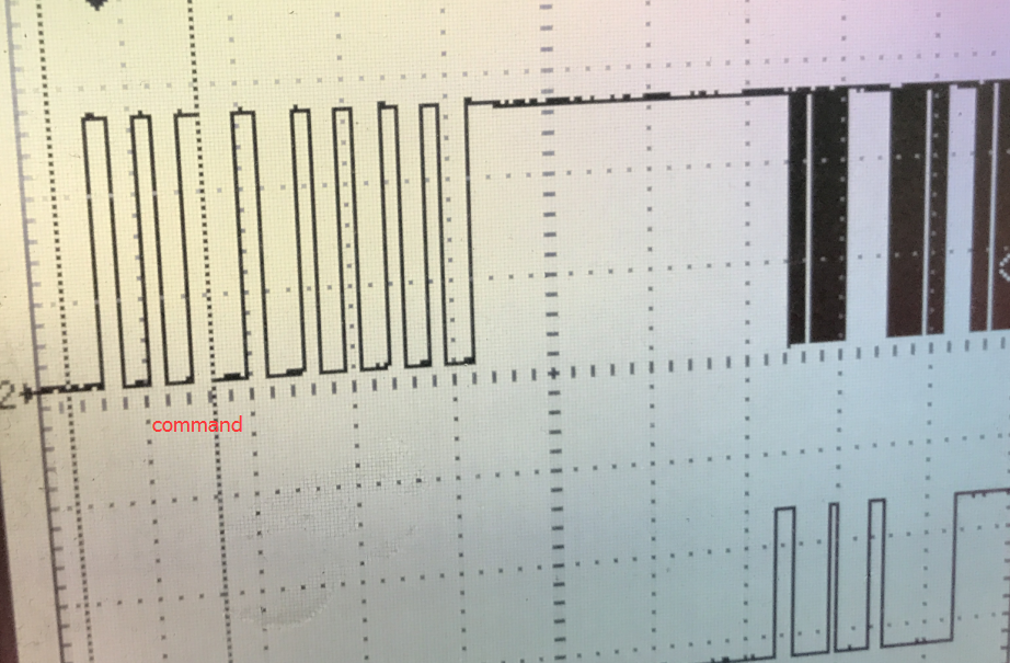
The TXCT and SICO signals in scope is as bellow:

It's strange that after 5 bytes transmitted, the 3 following bytes are coming with a bigger delay about 1ms or 3ms and values are random.

Could anyone point out what may cause the problem?

  • Hello,

    Have you been able to read/write any other pages successfully?

    When you say you've written 5 bytes via MCU, for full clarity, you mean writing 5 bytes from MCU into TMS37157 without using RF communication, correct? If so, did you verify you could read the bytes out correctly? Just sanity checking for starters...
  • hi~ thank you for replying.

    I’ve checked that 5 bytes are correctly written into TMS37157 using SPI Command.

    And I'm mostly confused that according to TMS37157 datasheet I should  receive a 10 bytes response, consist of  1 start bytes(7E), 1 selective address(00), 5 user bytes(whatever), 1 bytes Read Address, 2 bytes BCC.

    But I always get an 8 bytes response. And  the response seems to be discontinuous which is quite different from expected:

  • do you have a capture of what (bytes) you are getting? 

    screenshot above is from something i put together.

    you should be able to replicate with a 'scope on your side, too.


  • I‘ve changed my code to read page 3 from tms37157 so we can make a comparision between them.

    I got 7 bytes this time which is as blow:

    It's a zoom of signals in scope above.

    And the watch window of IAR tell me that the 7 bytes are 0x7E, 0xFF, 0x00, 0x0E, 0xD5, 0x00, 0x00. It's quite the same as the scope implied.

    It seems to me that whatever page I read from TMS37157, the response data become weird after 5 bytes transmitted.  

    I have no idea what may be the problem.

  • can you show right before you turn the TX on?
    i am looking for you to have sent the Tinit pulse

    like what is shown in FIgure 5.1 here www.ti.com/.../tms3705
    hope that helps - its quick educated guess
  • As you can see,diagnosis phase is not recorded in the scope. But I am sure diagnosis is performed well because I wrote my code in such a logic that read phase is carried out if only 0xAF is received in diagnosis phase.

    I'll upload screeshot of diagnosis part as soon as possible after I finish my business travel.

    Besides,I trimmed tms37157 again after my last post. Trimmed byte change to 0x6c from 0x58. And the response of tms37157 changed too. Sometimes no response at all,sometimes 10 or 9 or 7 bytes received if I change the position of tms37157 slightly.
    I am wondering whether the parameters of RF passive component on tms3705 side are not best matched,like Q factor or resonate frequency .
  • i see - its a good point - with the TMS3705, you need to be low Q (to limit current mostly) - with an inductor between 400-700uH. Then calculate for resonance, populate, check, and fine tune if necessary. Both sides should be tuned or "trimmed" . Use the development kit to trim the PaLFI devices so you can eliminate that being any part of the issue. 

  • Thank you for your advice.

    I'll try and post it here if any progress is made.

  • Hi~

    Being busy with another project for some time, the research into communication between TMS37157 and TMS3705 has been delayed .

    According your last advice,I replaced series resistors with antenna from 4.7Ω to 22Ω to lower Q factor of antenna with TMS3705. Then communication seemed to be in better case.

    Reading Page 9, I got response as below:
    start bytes (1 byte)| Page 2(1 byte)| UserData(5 byte) |ReadAddr(1Bytes)| FrameBCC(2Byte)
    0x7E | 0x00 | 0x4F,0x50,0x51,0x52,0x53| xxx(random) | xxx(random)

    And what exactly I expected to get is this:
    start bytes (1 byte)| Page 2(1 byte)| UserData(5 byte) |ReadAddr(1Bytes)| FrameBCC(2Byte)
    0x7E | 0x00 | 0x4F,0x50,0x51,0x52,0x53| 0x24 | 0x75,0x5C

    ReadAddr in response I got can sometimes be correct(i.e. =0x24). But FrameBCC I got always seems to be random and meaningless.

    Beside, I've found something interesting that response became strange whether I make antenna distance larger or smaller. In my opinion, smaller distance will always make communication easier. Correct me if I am wrong.

    I'll adjust series resistors to some other values to find the difference. And any advice from you is appreciated.
  • Dear user4894977 -
    Based on the data you apparently programmed into the device on page 9, I would agree the CRC value should be 0x5C75

    I never said to use resistors in series with the antenna, though, only that the antenna should be low Q. This means use skinny wire, like 30AWG magnet wire or similar wire to make a coil between 400uH to 700uH versus using thicker wire and a lower inductance (like what is used with the higher power readers.

    See data sheet for reference and check against what you have created ==> www.ti.com/.../tms3705.pdf (page 17)
  • OK, thank you for your advice.

    I'm quite new in RFID communication. Could you please tell me that why in my experiment smaller distance makes communication more difficult not easier? Or it's also associated with the antenna  problem? 

    In my project, the distance is required to be among 5mm and 20mm, however my design now only worked(means that only user data ,not  including CRC, correctly received) when communication distance is among 15mm and 30mm.

    Here is something about antenna I used:

    for TMS3705: antenna size : 32mm*43mm;  inductance :  425uH; wire diameter: 0.2mm; cable length: 150mm; Resistance: 6.7Ω; Circles: not sure;

    And here goes the picture:

  • surely you are using resonance capacitor??
    where is that located? Did you confirm you are resonant at 134.2kHz? Did you measure the inductance in the correct frequency range?

    its hard to see in the picture - but i think i see you did not twist the wires on the "tail" here. This will cause you issues as well.
  • Capacitor is not included in the picture. It's mounted on a demo PCB.

    And the schematic:

    The waveform  of L2. I measured is like this:

    Maybe you can help me figure out whether the antenna is working well or not.

    And I wonder that since response from responder is uploaded during discharge phase, can it be the cause that the duration of discharge phase is too short so that the last three or four bytes can't be successfully uploaded ?

    Thank you again for your patience.

  • i would remove R3 and C2 (in your schematic) and short one or both of them. (see below)  - the wave should be as close to perfect sine wave when you are correct - here you show a little peaky top and you are off frequency a bit. it really matters to get it as close to 134.2kHz as possible. With 3.3nF, you really need that coil to be at 426.5uH to get to 134.2kHz (per the math)

    on your schematic - make either C10 or C11 a second 22uF

    with regards to the LF coil. Its generally better to not have long leads like that - and in your case i would recommend you twist the wires, heatshrink or ziptie them

    see below

  • also, please realize you are going to push a bit of current here. if you keep the 4.7Ohm resistors, switch to larger (we used 1206 size parts on the design above), as well as the 3.3nF part, which should be an NP0/C0G type, capable of handling 50V (at least).
  • I’ve  done what exactly you suggested, twisting the lead, removing R3 and C2 then shorting both of them, replace C10 with a 22uF capacitor. Beside I adds a  paralleling capactitor to CR, and the frequency changed from 135.1 to 134.4, a bit closer to 134.2. However things didn't go any better.

    Then I started put my focus on reviewing design of responder. After looking into waveform of RF pin on TMS37157, I was confirmed that response was not sent completely. The waveform is as below:

    A response from TMS37157 will always be 96 bit which make the duration about 12.2ms. Compared to the waveform of a properly working read action from online document as below,  I believe that something goes wrong with responder.

    I wonder why amplitude of my response waveform keeps decreasing and then suddenly disappers, ending with a 2V constant level. It seems that responder stops response by itself. Can it be a antenna problem?

    Here goes design of responder :

  • Finally the problem was found.
    Capactitor CR I used is not really NP0 type as it is marked. Capacitor changed, problem solved.
    Thanks to your help!