This thread has been locked.

If you have a related question, please click the "Ask a related question" button in the top right corner. The newly created question will be automatically linked to this question.

Determining Phase Offset using CC430

Other Parts Discussed in Thread: CC430F6137, CC1101, SIMPLICITI, CC2400

Forgive me if this has been answered elsewhere, if the answer is obvious, or if my logic is wrong. RF communication is not my expertise. That's why I'm asking you smart folks.

We are using the CC430F6137 SOC. The CC430 Family User Guide states:

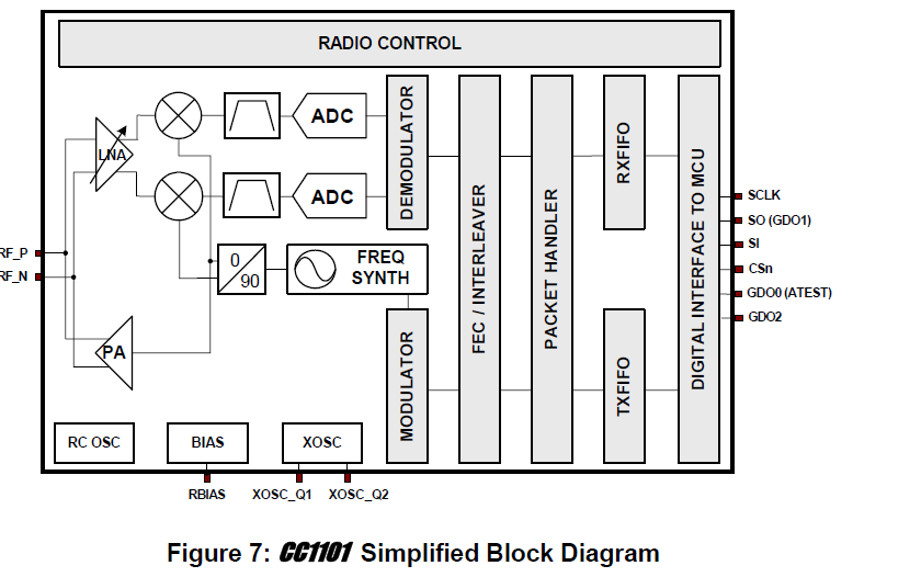
"The CC1101-based radio core features a low intermediate frequency (IF) receiver. The received radio frequency (RF) signal is amplified by the low-noise amplifier (LNA) and down-converted in quadrature (I and Q) to the IF. At IF, the in-phase/quadrature-phase (I/Q) signals are digitized by the ADCs. Automatic gain control (AGC), fine channel filtering, and demodulation bit/packet synchronization is performed digitally."

Upon receiving a message I need to determine the phase offset between the incoming frequency and that of the internal local oscillator frequency assuming the frequencies are the same. Is this information accessible in a register or anywhere else? I assume the radio module is accounting for the phase offset somewhere under the hood.

I know that the frequency offset information is available via FREQEST (Frequency Offset Estimate From Demodulator), but that doesn't help much.

Alternatively, is it possible to access the I/Q signals before or after passing through the ADCs? The latter would require the ability to access the radio module interal ADC memory registers. Those are completely separate from the ADC12_A module memory registers, right?

Thanks in advance for you help!

  • Jeff, 

    The radio portion of the chip is a complete transceiver which contains a complete RF modulator/demodulator. The transceiver contains its own RF ADC and DAC's, it also contains all the circuits for successfully receiving an RF signal. The special case of the CC430xxxx family of devices is that the CC1101 transceiver has been integrated in a MSP430 making a RF SOC we are calling CC430xxxx. Below is a simplified block diagram of the CC1101, here you will note the common I/Q based down converter chain, with corresponding ADC and demodulator. 

    So using the CC430xxxx series of devices the user has to set the transceiver up by programing a series of registers that control the behavior of the device. I recommend starting with recommended settings for SmartRF Studio 7.x. After the radio has been setup all you have to do is load data into the TX FIFO and retrieving data from the RX FIFO. 

    Furthermore the ADC12A that you refer to is completely separate from the RF section and is intended to be used by the user to perform actual measurements on whatever you desire the system to measure. Then you can write code that transfers the results from the ADC12 into the TX FIFO for transmission to you end destination.

    I hope this helps.

    /TA

  • Thanks a lot for your reply.

    I use SimpliciTI for communicating between devices and it works like a charm. I am aware of SmartRF Studio but I have not had a need to change the default radio setting yet.

    I've been staring at the CC1101 block diagram for a few days now. Is there a way to access any of the signals passed through the I/Q down converter chain during runtime in firmware?

    This is the core problem, as stated by one of my superiors:

    "Upon receiving a message I need to determine the phase offset between the incoming frequency and that of the internal local oscillator frequency assuming the frequencies are the same."

    When a message is transmitted between two devices configured to operate at the same frequency there might be a slight difference between the transmitter frequency and receiver frequency. The CC1101 demodulator compensates for this difference and sets the FREQEST register value to reflect the value of the difference.

    That's all fine and good, but in addition to the frequency difference there may be an associated phase difference. For example:


    I'm sure the demodulator accounts for the phase difference as well. It would be nice if the value was stored in a register like the frequency difference.

    The reason we need the phase difference value is because it provides a semi-unique key between pairs of communicating devices. The phase difference is affected by the distance between devices and other conditions.

  • Jeff, 

    The only device in the CCxxxx lineup that I know of that allows you to get access to both I and Q signals is the CC2400. It has an options to route the analog version of both I and Q out at the same time. 

    /TA

  • Very cool. I checked the data sheet for the CC2400. Under the "General Purpose / Test Output Control Pins" section the PD_F_COMP "Phase detector comparator output" signal is listed. What is the value of this signal? Specifically, which two signals are being compared to calculate its value and when are they compared?

  • Okay, I think that a little more information about what you wish to accomplish is needed, but from the data sheet:

    "The CC1101-based radio core features a low intermediate frequency (IF) receiver. "

    From the above statement, the local oscillator (VCO) is never the same frequency as the incoming signal, if it were, that would be a zero IF receiver and then there would be a potential phase relationship (still probably not as there are always going to be some variance in frequency unless you synced the PLL to the incoming signal but then since it would be tracking that, you would not get any useful information out of it.

    In general phase offset is something that doesn't matter, in a zero IF situation it becomes a DC signal, in a low IF situation, since the two waveforms are asynchronous, it doesn't matter.

  • Based on what I've read, the IF signal is created by mixing the incoming RF signal with the VCO signal. The PLL is synced to an external oscillator (XOSC) reference signal and generates the VCO output.

    Chris, what you're saying is that syncing the PLL to the incoming RF signal (instead of the XOSC signal) wouldn't do any good because then the PLL output would be in-phase with the RF signal; we can't use signals that are in-phase to determine phase offset.

    Also, since FIF = FRF – FVCO, if the VCO signal was the same as the RF signal then the IF signal would be a zero DC signal and contain no useful information.

    Additionally, comparing the phase of two waveforms that don't share the same frequency doesn't make much sense.

    It seems that one option is to capture the RF signal before it is converted into the IF and compare it to an external reference signal with the expected communication frequency. Of course that assumes nearly zero variance in frequency between the expected and received RF signals.

    After the received RF signal is down-converted in quadrature (I and Q) to the IF all useful phase offset information is lost, right? In other words, those signals are in-phase with the XOSC reference signal.

  • Jeff Robble said:

    Based on what I've read, the IF signal is created by mixing the incoming RF signal with the VCO signal. The PLL is synced to an external oscillator (XOSC) reference signal and generates the VCO output.

    Chris, what you're saying is that syncing the PLL to the incoming RF signal (instead of the XOSC signal) wouldn't do any good because then the PLL output would be in-phase with the RF signal; we can't use signals that are in-phase to determine phase offset.

    Also, since FIF = FRF – FVCO, if the VCO signal was the same as the RF signal then the IF signal would be a zero DC signal and contain no useful information.

    Additionally, comparing the phase of two waveforms that don't share the same frequency doesn't make much sense.

    It seems that one option is to capture the RF signal before it is converted into the IF and compare it to an external reference signal with the expected communication frequency. Of course that assumes nearly zero variance in frequency between the expected and received RF signals.

    After the received RF signal is down-converted in quadrature (I and Q) to the IF all useful phase offset information is lost, right? In other words, those signals are in-phase with the XOSC reference signal.

    I am thinking about this...but pretty much I believe the answers are yes to all of the above. Things like RADAR work well as the source of the RF is also used to measure against, so that makes it pretty straight forward, but with a second source, especially one that is not super accurate, it is harder to tell what is drift and what is phase shift.

  • Here detectorall is also a good place to buy a metal detector, and there are different types for you to choose from , There are many kinds of detectors, such as handheld metal detectors, safety metal detectors, walk through metal detectors,gold metal detectors, rf signal detector,  X-Ray inspection systems and so on.