Other Parts Discussed in Thread: MSP430G2553, , , RF430CL330H, RF430CL331H
Tool/software: Code Composer Studio
Hi,
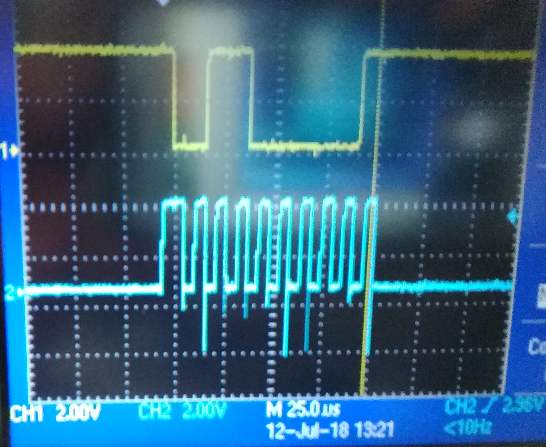
I am facing Issue in I2C communication between MSP430G2553 and MSP430FRL152H . I am using MSP430FRL152H as a slave device.
For Master : i have picked example code from \slac485j\MSP430G2xx3_Code_Examples\C\msp430g2xx3_uscib0_i2c_08.c
/* --COPYRIGHT--,BSD_EX
 * Copyright (c) 2012, Texas Instruments Incorporated
 * All rights reserved.
 *
 * Redistribution and use in source and binary forms, with or without
 * modification, are permitted provided that the following conditions
 * are met:
 *
 * *  Redistributions of source code must retain the above copyright
 *    notice, this list of conditions and the following disclaimer.
 *
 * *  Redistributions in binary form must reproduce the above copyright
 *    notice, this list of conditions and the following disclaimer in the
 *    documentation and/or other materials provided with the distribution.
 *
 * *  Neither the name of Texas Instruments Incorporated nor the names of
 *    its contributors may be used to endorse or promote products derived
 *    from this software without specific prior written permission.
 *
 * THIS SOFTWARE IS PROVIDED BY THE COPYRIGHT HOLDERS AND CONTRIBUTORS "AS IS"
 * AND ANY EXPRESS OR IMPLIED WARRANTIES, INCLUDING, BUT NOT LIMITED TO,
 * THE IMPLIED WARRANTIES OF MERCHANTABILITY AND FITNESS FOR A PARTICULAR
 * PURPOSE ARE DISCLAIMED. IN NO EVENT SHALL THE COPYRIGHT OWNER OR
 * CONTRIBUTORS BE LIABLE FOR ANY DIRECT, INDIRECT, INCIDENTAL, SPECIAL,
 * EXEMPLARY, OR CONSEQUENTIAL DAMAGES (INCLUDING, BUT NOT LIMITED TO,
 * PROCUREMENT OF SUBSTITUTE GOODS OR SERVICES; LOSS OF USE, DATA, OR PROFITS;
 * OR BUSINESS INTERRUPTION) HOWEVER CAUSED AND ON ANY THEORY OF LIABILITY,
 * WHETHER IN CONTRACT, STRICT LIABILITY, OR TORT (INCLUDING NEGLIGENCE OR
 * OTHERWISE) ARISING IN ANY WAY OUT OF THE USE OF THIS SOFTWARE,
 * EVEN IF ADVISED OF THE POSSIBILITY OF SUCH DAMAGE.
 *
 *******************************************************************************
 *
 *                       MSP430 CODE EXAMPLE DISCLAIMER
 *
 * MSP430 code examples are self-contained low-level programs that typically
 * demonstrate a single peripheral function or device feature in a highly
 * concise manner. For this the code may rely on the device's power-on default
 * register values and settings such as the clock configuration and care must
 * be taken when combining code from several examples to avoid potential side
 * effects. Also see www.ti.com/grace for a GUI- and www.ti.com/msp430ware
 * for an API functional library-approach to peripheral configuration.
 *
 * --/COPYRIGHT--*/
//******************************************************************************
//  MSP430G2xx3 Demo - USCI_B0 I2C Master TX multiple bytes to MSP430 Slave
//
//  Description: This demo connects two MSP430's via the I2C bus. The master
//  transmits to the slave. This is the master code. It continuously
//  transmits an array of data and demonstrates how to implement an I2C
//  master transmitter sending multiple bytes using the USCI_B0 TX interrupt.
//  ACLK = n/a, MCLK = SMCLK = BRCLK = default DCO = ~1.2MHz
//
//  *** to be used with "msp430g2xx3_uscib0_i2c_09.c" ***
//
//                                /|\  /|\
//               MSP430G2xx3      10k  10k     MSP430G2xx3
//                   slave         |    |        master
//             -----------------   |    |  -----------------
//           -|XIN  P3.1/UCB0SDA|<-|---+->|P3.1/UCB0SDA  XIN|-
//            |                 |  |      |                 |
//           -|XOUT             |  |      |             XOUT|-
//            |     P3.2/UCB0SCL|<-+----->|P3.2/UCB0SCL     |
//            |                 |         |                 |
//
//  D. Dang
//  Texas Instruments Inc.
//  February 2011
//   Built with CCS Version 4.2.0 and IAR Embedded Workbench Version: 5.10
//******************************************************************************
#include <msp430.h>

unsigned char *PTxData;                     // Pointer to TX data
unsigned char TXByteCtr;
const unsigned char TxData[] =              // Table of data to transmit
{
  0x11,
  0x22,
  0x33,
  0x44,
  0x55
};

int main(void)
{
  WDTCTL = WDTPW + WDTHOLD;                 // Stop WDT
  P1SEL |= BIT6 + BIT7;                     // Assign I2C pins to USCI_B0
  P1SEL2|= BIT6 + BIT7;                     // Assign I2C pins to USCI_B0
  UCB0CTL1 |= UCSWRST;                      // Enable SW reset
  UCB0CTL0 = UCMST + UCMODE_3 + UCSYNC;     // I2C Master, synchronous mode
  UCB0CTL1 = UCSSEL_2 + UCSWRST;            // Use SMCLK, keep SW reset
  UCB0BR0 = 12;                             // fSCL = SMCLK/12 = ~100kHz
  UCB0BR1 = 0;
  UCB0I2CSA = 0x48;                         // Slave Address is 048h
  UCB0CTL1 &= ~UCSWRST;                     // Clear SW reset, resume operation
  IE2 |= UCB0TXIE;                          // Enable TX interrupt

  while (1)
  {
    PTxData = (unsigned char *)TxData;      // TX array start address
    TXByteCtr = sizeof TxData;              // Load TX byte counter
    while (UCB0CTL1 & UCTXSTP);             // Ensure stop condition got sent
    UCB0CTL1 |= UCTR + UCTXSTT;             // I2C TX, start condition
    __bis_SR_register(CPUOFF + GIE);        // Enter LPM0 w/ interrupts
                                            // Remain in LPM0 until all data
                                            // is TX'd
  }
}

//------------------------------------------------------------------------------
// The USCIAB0TX_ISR is structured such that it can be used to transmit any
// number of bytes by pre-loading TXByteCtr with the byte count. Also, TXData
// points to the next byte to transmit.
//------------------------------------------------------------------------------
#if defined(__TI_COMPILER_VERSION__) || defined(__IAR_SYSTEMS_ICC__)
#pragma vector = USCIAB0TX_VECTOR
__interrupt void USCIAB0TX_ISR(void)
#elif defined(__GNUC__)
void __attribute__ ((interrupt(USCIAB0TX_VECTOR))) USCIAB0TX_ISR (void)
#else
#error Compiler not supported!
#endif
{
  if (TXByteCtr)                            // Check TX byte counter
  {
    UCB0TXBUF = *PTxData++;                 // Load TX buffer
    TXByteCtr--;                            // Decrement TX byte counter
  }
  else
  {
    UCB0CTL1 |= UCTXSTP;                    // I2C stop condition
    IFG2 &= ~UCB0TXIFG;                     // Clear USCI_B0 TX int flag
    __bic_SR_register_on_exit(CPUOFF);      // Exit LPM0
  }
}
For Slave: Source code:
/*
 * main.c
 *
 * RF430FRL152H NFC Only Example Project
 *
 * Copyright (C) 2014 Texas Instruments Incorporated - http://www.ti.com/
 *
 *
 *  Redistribution and use in source and binary forms, with or without
 *  modification, are permitted provided that the following conditions
 *  are met:
 *
 *    Redistributions of source code must retain the above copyright
 *    notice, this list of conditions and the following disclaimer.
 *
 *    Redistributions in binary form must reproduce the above copyright
 *    notice, this list of conditions and the following disclaimer in the
 *    documentation and/or other materials provided with the
 *    distribution.
 *
 *    Neither the name of Texas Instruments Incorporated nor the names of
 *    its contributors may be used to endorse or promote products derived
 *    from this software without specific prior written permission.
 *
 *  THIS SOFTWARE IS PROVIDED BY THE COPYRIGHT HOLDERS AND CONTRIBUTORS
 *  "AS IS" AND ANY EXPRESS OR IMPLIED WARRANTIES, INCLUDING, BUT NOT
 *  LIMITED TO, THE IMPLIED WARRANTIES OF MERCHANTABILITY AND FITNESS FOR
 *  A PARTICULAR PURPOSE ARE DISCLAIMED. IN NO EVENT SHALL THE COPYRIGHT
 *  OWNER OR CONTRIBUTORS BE LIABLE FOR ANY DIRECT, INDIRECT, INCIDENTAL,
 *  SPECIAL, EXEMPLARY, OR CONSEQUENTIAL DAMAGES (INCLUDING, BUT NOT
 *  LIMITED TO, PROCUREMENT OF SUBSTITUTE GOODS OR SERVICES; LOSS OF USE,
 *  DATA, OR PROFITS; OR BUSINESS INTERRUPTION) HOWEVER CAUSED AND ON ANY
 *  THEORY OF LIABILITY, WHETHER IN CONTRACT, STRICT LIABILITY, OR TORT
 *  (INCLUDING NEGLIGENCE OR OTHERWISE) ARISING IN ANY WAY OUT OF THE USE
 *  OF THIS SOFTWARE, EVEN IF ADVISED OF THE POSSIBILITY OF SUCH DAMAGE.
 *
*/

#include "NDEF.h"
#include "types.h"
#include "patch.h"
#include <rf430frl152h.h>


#define PORT_I2C_OUT    P1OUT
#define PORT_I2C_DIR    P1DIR
#define PORT_I2C_SEL0   P1SEL0
#define PORT_I2C_SEL1   P1SEL1
#define SDA BIT0
#define SCL BIT1


//*****************************FUNCTION PROTOTYPES********************************/
void DeviceInit(void);
//********************************************************************************/


#pragma RETAIN(PRxData);
unsigned char *PRxData;                     // Pointer to RX data
#pragma RETAIN(RXByteCtr);
unsigned char RXByteCtr;
#pragma RETAIN(RxBuffer);
volatile unsigned char RxBuffer[128];       // Allocate 128 byte of RAM


void I2C_init(void);

void main()
{
    WDTCTL = WDTPW + WDTHOLD;                   // Stop watchdog

    // ROM RF13M module setup ** The following three lines are needed for proper RF stack operation
    DS = 1; 									// ROM variable needs to be initialized here
    asm ( " CALL #0x5CDA "); 					// Call ROM function ( Initialize function pointers)
    asm ( " CALL #0x5CAC "); 					// Call ROM function ( Check part configuration)


	initISO15693(CLEAR_BLOCK_LOCKS);  // clear all block locks
	//initISO15693(0);					// leave block locks as they are set in FRAM

	//JTAG is set to be disabled in this function call
	DeviceInit();

	//CopyFRAMtoNDEF();

	I2C_init();

    __bis_SR_register(GIE);

	while(1)
	{
	    PRxData = (unsigned char *)RxBuffer;    // Start of RX buffer
	    RXByteCtr = 0;                          // Clear RX byte count
	    __bis_SR_register(LPM3_bits + GIE);
	}
}

/**************************************************************************************************************************************************
*  DeviceInit
***************************************************************************************************************************************************
*
* Brief : Initialize the clock system and other settings
*         Patchable function
*
* Param[in] :   parameters:  has these independent options
*                            INITIALIZE_DEVICE_CLOCK_SYSTEM - initializes the clock system
*                            POPULATE_INTERRUPT_VECTOR_IN_INITIALIZATION - populate the default interrupt vectors and recalculate their CRC
*
* Param[out]:  None
*
* Return  None
*
* Patchable :   Yes
**************************************************************************************************************************************************/

void DeviceInit(void)
{
	P1SEL0 = 0xF0; //keep JTAG
	P1SEL1 = 0xF0; //keep JTAG
//	P1SEL0 = 0x00; //no JTAG
//	P1SEL1 = 0x00; //no JTAG
    P1DIR &= ~0xEF;
    P1REN = 0;

    CCSCTL0 = CCSKEY;                        // Unlock CCS

    CCSCTL1 = 0;                             // do not half the clock speed
    CCSCTL4 = SELA_1 + SELM_0 + SELS_0;      // Select VLO for ACLK and select HFCLK/DCO for MCLK, and SMCLK
    CCSCTL5 = DIVA_2 + DIVM_1 + DIVS_1;      // Set the Dividers for ACLK (4), MCLK, and SMCLK to 1
    CCSCTL6 = XTOFF;                         // Turns of the crystal if it is not being used
    CCSCTL8 = ACLKREQEN + MCLKREQEN + SMCLKREQEN; //disable clocks if they are not being used

    CCSCTL0_H |= 0xFF;                       // Lock CCS

  return;
}


void I2C_init(void)
{
    //ROM sets P1OUT = 0x0F, this then consumes some current
    P1OUT = 0x00; // needed to reduce power consumption on RF430FRL152H EVM, since P1.3 is connected to a 2.2K Ohm resistor on the EVM to ground

    // Configure P1.0 and P1.1 pins for I2C mode
    PORT_I2C_SEL0 |= SCL + SDA;
    PORT_I2C_SEL1 &= ~(SCL + SDA);

    UCB0CTL1 |= UCSWRST; // eUSCI_B in reset state
    UCB0CTLW0 |= UCMODE_3; // I2C slave mode
    UCB0I2COA0 = 0x0048; // own address is 12hex

//      P2SEL |= 0x03; // configure I2C pins (device specific)

    UCB0CTL1 &= ~UCSWRST; // eUSCI_B in operational state
//    UCB0IE |= UCTXIE + UCRXIE; // enable TX&RX-interrupt
    UCB0IE |= UCTXIE;

    __bis_SR_register(GIE); // general interrupt enable

        return;
}


#pragma vector = RF13M_VECTOR
__interrupt void RF13M_ISR(void)
{
     switch(__even_in_range(UCB0IV,0x1e)) {
     case 0x00: // Vector 0: No interrupts
     break;

     case 0x16:  // Vector 22: RXIFG0
         UCB0STAT &= ~(UCSTPIFG + UCSTTIFG);       // Clear interrupt flags
         if (RXByteCtr)                            // Check RX byte counter
//            __bic_SR_register_on_exit(CPUOFF);      // Exit LPM0 if data was

       __bic_SR_register_on_exit(LPM0_bits | GIE); // Exit LPM0


     break;
     case 0x18:  // Vector 24: TXIFG0

         *PRxData++ = UCB0RXBUF;                   // Move RX data to address PRxData
         RXByteCtr++;                              // Increment RX byte count


     break;

     default: break;
     }

}
I am not able to receive T2C Rx/Tx interrupt. At SCL and ADA pin , 30k pullup is connected at master end (EXP430G2 lanch pad) and 2.2K pullup is connected on slave end (RF430FRL152HEVM board).
kindly provide any hint for go ahead.
Thanks,
AG