This thread has been locked.

If you have a related question, please click the "Ask a related question" button in the top right corner. The newly created question will be automatically linked to this question.

TRF7970A: Code for TRF7970AEVM in Direct Mode 0

Part Number: TRF7970A
Other Parts Discussed in Thread: DLP-7970ABP

Hi,

I am using example code received from this link: http://www.ti.com/tool/trf796x_trf7970x_mifare_12_2013  (TRF7970A_Parallel_SPI_Firmware_MIFARE-OK)


This example code use SDM and DM1 for MIFARE classic card block read.

We are getting issue when move from SDM to DM1, Clock not generated by TRF7970A and getting timeout event.

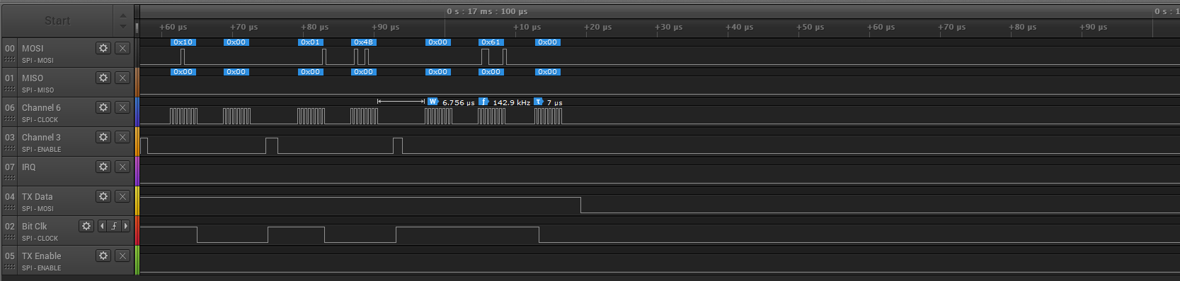
Verified waveform on logic Analyzer.

In Special Direct Mode send 4 byte with parity bit is working fine.

Then after send command to stop the SDM and then start DM1 but CLK on I/O_5 not generated by TRF7970A.


All command sent on SPI is verified so How can I debug this issue? 


Thanks,

Nirav Patel

  • Hello Nirav,

    Please see Section 4.3 of our Special Direct Mode app note which lays out all the details on how to correctly enter DM1: www.ti.com/.../sloa214
  • Hi Ralph.

    I have the same issue as Nirav described. I've ported the sloa214 example code to our PIC24FJ256GB610. The only modification I did was the SPI handling and mcu.h defines to accommodate our controller. Here is how the signals look after Entering DM1:


    As you can see, the steps 14,15,16,17,18 are performed as described in Application Note. Also, I made sure that all the other steps looks the same on logic analyzer as in Application Note. After step 18, there is no activity on SDM Bit Clock line. I'm using PIC24FJ256GB with DLP-7970ABP.

    Can you help us with this issue?

  • Hello Ion,

    When porting to other MCU's we have found that SDM and DM1 entry is extremely timing dependent. You need to compare the timings for what works with MSP430 MCU's to what you have for the PIC. If you don't have a TRF7970AEVM to test with, I can provide a saleae file for this so you can compare, however I will only be able to do that once back in the office on Monday.
  • Hi Ralph,

    By SDM and DM1 entry timings, you mean the time between transitions?. We are using the PIC at 16MHz instruction speed, which I believe is two times faster than the MSP430 for which the example was written. We don't have a TRF7970AEVM so I think a saleae file would be very helpful for us. We will also try a much faster MCU to check if the timings are the issue. Please don't close this ticket until we find a solution. Thank you.

    Ion Popa

  • Hi Ralph,
    You said you can send the saleae file so we can compare against our setup. Can you please send that file?
  • Hello Ion,

    Sorry about the delay on that, I thought I had the file already but I don't so I have to remeasure it and haven't quite got the chance yet, this post is open and on my to-do list and I am going to try and get that capture taken later today.
  • Hello Ion,

    Here is the logic capture file: https://e2e.ti.com/cfs-file/__key/communityserver-discussions-components-files/667/MIFARE_5F00_Classic_5F00_SDM_5F00_Auth.logicdata

    I labeled the signals to describe them like the app note.

  • Hi Ralph,

    I checked your logic file with my capture and it looks exactly the same (except the UID, which is normal). Also, the timings are approximately the same. I've attached my logic capture. Can you take a look on that? Maybe I missed something when I compared the captures.

    pic_nfc.zip

  • Hello Ion,

    I would look into expanding the time between the point of entering SDM with the 8 clock cycles and bringing up the TX Enable line high. While its only in microseconds, that is happening almost twice as fast.

    Also it dawned on me that you would be using the MIFARE .lib with a PIC MCU, is that able to compile on an MCU with such a different architecture correctly? That lib was generated specifically for an MSP430...
  • Hi Ralph,

    I Added another dummy write of 8 clock cycles, but with no success. I have the source files for Mifare.lib (made a request) and added the source files directly in my project(crypto1.h, crypto1_clean.c, crypto1.c). Also, today I've ported the sloa214 example to a STM32F103 controller, clocked at 72MHz and its getting stuck at the same sequence. 

  • Hello Ion,

    I wouldn't do dummy clocks, just delay wait states, I don't like the idea of dummy clocks as I am not sure how the device would register those.

    Okay, good to know you have the source files at least.
  • So, as per your recommendation, I added a measured delay instead of dummy clocks and still no success. I have no clue whats happening here...
  • Hello Ion,

    I am going to check with the main developer of the firmware, but he is in a different team now so I can't guarantee I'll get face to face time with him until next week to review the file you sent me.
  • Hello Ion,

    I discussed this with the original developer but neither of us were able to uncover any clear issues that would explain the behavior. Unfortunately as the issue is occurring on a non-TI MCU and we do not have knowledge with it, it is not possible for us to offer any detailed support regarding this issue.

    The best advice I can give would be to step-by-step review all the key transitions outlined within the app note and if there are any timing discrepancies, especially in any areas that the TI example code has inserted a delay, to resolve those to get the timings to align with how the code runs on the MSP430 MCU.