This thread has been locked.

If you have a related question, please click the "Ask a related question" button in the top right corner. The newly created question will be automatically linked to this question.

problem with tms3705 transponder write protocol

Other Parts Discussed in Thread: MSP430F1232, TMS3705

HI.

Time write pulse pause always longer than set.

In case write pulse pause set 170us, realy pause is 75us.

Could anyone suggest me a solution for this problem ?

Thanks.

Ivan.

  • Hi, have you solve the problem? I can´t program any R/W tag. Do you have some functional code to share it? Thx!

  • Ivan/Jan -

    have a look at the LF.c file (see LF.init function) in the ez430-TMS37157 project on that product page. this is for MSP430F1232 driving TMS3705. You can use this as example here and change PWM timings in that file to match what the RO/RW tags want  to see.

    For example:

    //for RO_RW_tags:

    //for RO_RW_tags, JDW 09/17/2010
    PWMtimes.usToffH  = 1000;
    PWMtimes.usTonH   = 1000;
    PWMtimes.usToffL  = 300;
    PWMtimes.usTonL   = 1700;
     

    To program data into the EEPROM of an R/W configured tag, the 134 kHz carrier signal is again turned on for typically 50 ms. Immediately after this time, the reader modulates the transmission to instruct the tag to prepare to be programmed by the data sent in the Write Address and Write Password fields. The 80-bits of write data are then passed to the tag by a further modulation of the carrier signal and finally the transmitter is turned on 100% again for 15 ms to provide the energy to ‘blow’ the data into EEPROM.


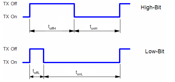
    The reader uses OFF/ON modulation to pass data to a transponder. The relationship between the carrier’s ON time to the OFF time signifies the value that is being passed.


  •  Do you have some functional code of write tag????

  • which tags are you using? if R/W, MPT or MUSA, then you just need to respect the timings of the write, per the tag device. 

    for example: 

    Tag Type  toffL (μs) tonL (μs) toffH (μs)  tonH (μs)
    R/W and MPT 300 1700  1000 1000
    MUSA 170 330 480 520

    where the carrier modulation is looking like this:

    and this is the general form for programming the R/W transponders is:


    and this is the general form for programming the MPT transponders is:

    if you can indicate which transponders you are trying to write - then you can follow the form and/or we can help guide you further - thanks! 

  • I'm using RI-TRP-WFOB. Do you have some functional code?

  • here is the modified LF.c file that is what i brought up earlier in the thread. 

    //------------------------------------------------------------------------------
    //
    //  LF.c
    // 	Methods for LF communication via the TMS3705 frontend and the LF antenna drivers.
    //  Currently uses the Immobilizer antenna only.
    //
    // 	Juergen Austen
    //  Texas Instruments, Inc
    //  December 2008
    //
    //------------------------------------------------------------------------------
    #include  <msp430x12x.h>
    #include  <defines.h>
    #include  <Board defines.h>
    
    
    // variables
    struct stPWM	PWMtimes  = {100, 550, 100, 250};	
    struct stBLC 	BLCtimes  = {100, 300, 550, 600};	
    
    //struct stBLC 	PEtimes		= {100, 250, 550, 0};	
    unsigned char	ucMCW1 = 0x7C, ucMCW2 = 0x7C;		// Mode Control Write byte(s)
    unsigned int 	uiStopCondition;
    
    extern struct stTimerCtrl     	TimerCtrl;
    extern struct stPacket 			aPacket;
    extern struct stLFpacket	    aLFpacket;
    extern union  unCMD				command1;
    extern union  unCMD2			command2;
    extern struct stASCIIbuffer		USB_Buffer;
    
    void LF_Init(void)
    {
    //PWMtimes.usToffH  = 480; //for PaLFI
    //PWMtimes.usTonH   = 520;
    //PWMtimes.usToffL  = 170;
    //PWMtimes.usTonL   = 330;
    PWMtimes.usToffH  = 1000; //for RO_RW_tags, JDW 09/17/2010
    PWMtimes.usTonH   = 1000;
    PWMtimes.usToffL  = 300;
    PWMtimes.usTonL   = 1700;
    
    BLCtimes.usToff	  = 170;
    BLCtimes.usTonL	  = 230;
    BLCtimes.usTonH	  = 350;
    BLCtimes.usTonSC  = 600;
    
    ucMCW1 = 0x7C;
    ucMCW2 = 0x7C;
    }
    
    //------------------------------------------------------------------------------
    void SendByteLF(unsigned char byte)
    {
    	// 	Transmits a byte on TXCT (to TMS3705) by shifting from LSB to MSB.
    	//	Uses either PWM (for CET, Passive Entry devices) or PPM (for CETAES) bit timing.	
          unsigned int shift;
          
          /************************** PWM *****************************************/
          if ((command1.field.PPM_PWM == 0) || (command1.field.ucMode == PE_WP))
          {
            for (shift = 0x01; shift <= 0x80; shift <<= 1)
            {
              if (byte & shift)
                { // High bit
                      SetOutput(&P1OUT, P1_TXCT, HIGH, PWMtimes.usToffH, USEC, HALT);
                      SetOutput(&P1OUT, P1_TXCT, LOW ,  PWMtimes.usTonH,  USEC, HALT);                                
                }
              else
                {// Low bit
                      SetOutput(&P1OUT, P1_TXCT, HIGH, PWMtimes.usToffL, USEC, HALT);
                      SetOutput(&P1OUT, P1_TXCT, LOW ,  PWMtimes.usTonL,  USEC, HALT);
                }
            }
          }	
          /************************* PPM ******************************************/
          else if (command1.field.PPM_PWM == 1)
                    {
                            for (shift = 0x01; shift <= 0x80; shift <<= 1)
                            {
                                    if (byte & shift)
                                    { // High bit
                                            SetOutput(&P1OUT, P1_TXCT, HIGH, BLCtimes.usToff, USEC, HALT);
                                            SetOutput(&P1OUT, P1_TXCT, LOW , BLCtimes.usTonH, USEC, HALT);
                                    }
                                    else
                                    { // Low bit
                                            SetOutput(&P1OUT, P1_TXCT, HIGH, BLCtimes.usToff, USEC, HALT);
                                            SetOutput(&P1OUT, P1_TXCT, LOW , BLCtimes.usTonL, USEC, HALT);
                                    }
                            }
                    }
    }
    
    //------------------------------------------------------------------------------
    void WriteModeControlByte(unsigned char byte)
    {
    	// 	Write the Mode Control Byte (MCW) for the TMS3705.
    	//	Bit time is 128USEC.
    	
    	unsigned int shift;	
    	
    	for (shift = 0x01; shift <= 0x80; shift <<= 1)
    	{
    		if (byte & shift)
    			SetOutput(&P1OUT, P1_TXCT, HIGH, 128, USEC, HALT);	// High bit
    		else
    			SetOutput(&P1OUT, P1_TXCT, LOW,  128, USEC, HALT);	// Low bit
    	}
    }
    
    //------------------------------------------------------------------------------
    void DoPowerBurst(char number)
    {	// Mini-routine to deliver Power Burst[number] from the RX packet
    	// ATTENTION, number is one-based for better readability
        if ((command1.field.PPM_PWM == 1) && (number == 2))
        	SetOutput(&P1OUT, P1_TXCT, HIGH, BLCtimes.usToff, USEC, HALT);
        	
        SetOutput(&P1OUT, P1_TXCT, LOW, aLFpacket.usPowerBurst[number-1], MSEC, HALT);
          
    }
    
    //------------------------------------------------------------------------------
    void DownlinkLF(void)
    { //	Very similar counterpart to the NormalModeUSB routine.
    	//	Sends the processed packet over LF.	
    	unsigned char c;
    	  
    	if ((P1OUT & P1_TXCT) == 0) 	// if battery charge still active
    	{
    		SetOutput(&P1OUT, P1_TXCT, HIGH, 2, MSEC, HALT);		        // Start recieve Phase
    		SetOutput(&P1OUT, P1_TXCT, LOW, 50, USEC, HALT);		        // Interrupt recieve Phase
    		SetOutput(&P1OUT, P1_TXCT, HIGH, 110, MSEC, HALT);		        // Set TXCT high, 3705 goes to sleep phase 
    		SetOutput(&P1OUT, P1_TXCT, LOW, 50, USEC, HALT);		        // Set TCXT low and wait t_wake = 50us (must not exceed 120us!)
    		SetOutput(&P1OUT, P1_TXCT, HIGH, 3, MSEC, HALT);		        // Set TXCT high and wait t_init ~= 3ms
    		
    		WriteModeControlByte(ucMCW1);	
    	}
    	else
    	{	
    		// TMS3705 Wake Sequence
    		SetOutput(&P1OUT, P1_TXCT, LOW, 50, USEC, HALT);		        // Set TCXT low and wait t_wake = 50us (must not exceed 120us!)
    		SetOutput(&P1OUT, P1_TXCT, HIGH, 3, MSEC, HALT);		        // Set TXCT high and wait t_init ~= 3ms
    		WriteModeControlByte(ucMCW1);	
    	}


        P2OUT |= P2_EN_UCC;					// enable UCC Amplifier
           
    	DoPowerBurst(1);											                                        // Entering Charge phase : deliver Power Burst 1
    	
    	// ******************* Additional fields for special packet types ************
    	// Send extra data bytes in Battery Backup or Wake Pattern packets
    	if ((command1.field.ucMode == BBUP)	|| (command1.field.ucMode == PE_WP))							
    	{
    		for (c=0; c<aLFpacket.ucEXTRAbytes; c++)												
    			SendByteLF(aLFpacket.ucEXTRAdata[c]);							                        // send EXTRA data (either BBUP or WP)
    				
    		if (command1.field.ucMode == PE_WP)											                    // stop bit
    		{
    			SetOutput(&P1OUT, P1_TXCT, HIGH, PWMtimes.usToffL, USEC, HALT);
    			SetOutput(&P1OUT, P1_TXCT, LOW , PWMtimes.usTonL , USEC, HALT);
    		}
    		else
    			DoPowerBurst(4);																		                    	// for BBUP do Power Burst 4
    	}
    	
        if (command1.field.ucMode	== PE_noWP_26)
          {
    		SetOutput(&P1OUT, P1_TXCT, HIGH,  100,  USEC, HALT);		      	          // Init MC
    		SetOutput(&P1OUT, P1_TXCT, LOW ,  350,  USEC, HALT);								
          }
    	// Packets that contain a Power Burst 3
    	if ((command1.field.ucMode == BBUP) || (command1.field.ucMode == PE_WP) || (command1.field.ucMode == PE_noWP_26))
    		DoPowerBurst(3);
    
    	// ******************** All packet types : send main fields ******************
    	for (c=0; c < aLFpacket.ucTXbytes; c++)
    		  SendByteLF(aLFpacket.ucTXdata[c]);								          						  // output TX bytes
    	
    //Error only CETAES has a stop condition	if (command1.field.PPM_PWM == 1)
    //Error only CETAES has a stop condition	{
    //Error only CETAES has a stop condition		SetOutput(&P1OUT, P1_TXCT, HIGH, BLCtimes.usToff,  USEC, HALT);		      	// output Stop Condition
    //Error only CETAES has a stop condition		SetOutput(&P1OUT, P1_TXCT, LOW , BLCtimes.usTonSC, USEC, HALT);								
    //Error only CETAES has a stop condition	}
    
    	DoPowerBurst(2);
    	
    	if (!command2.field.KeepTXon)
    		{
    		 P1OUT |= P1_TXCT;
    		 P2OUT &= ~P2_EN_UCC;					// disable UCC Amplifier
    		}
    	else
    	{
    		P1OUT &= ~P1_TXCT;					// leave on RF Field
    		P2OUT |= P2_EN_UCC;					// ensable UCC Amplifier
    	}
    		
    	
    	// ********************* End *************************************************	              
    }


    //------------------------------------------------------------------------------
    int UplinkLF(void)
    {	// 	Clocks out data from TMS3705 (TXCT == clock in, SCIO == data bytes out).
    	//	Constructs aPacket with standard fields around this data.
    	//	Returns  0 if successful.
    	//	Returns -1 if no data is available (timeout condition).
    	unsigned char c, i,k, byte=0x00;
    	unsigned int  shift = 0x01;
    
    	USB_Buffer.ucLengthActual = 0;
    
    	// Get actual RX data, from field 3
    	for (c=3; c < USB_Buffer.ucRXbytes+3; c++)		// No. of RX bytes
    	{
              TimerAWait_CCR2(20000, CONTINUE);			// Start the timeout in case there is no response 5000 => 5ms
              while (((P1IN & P1_SCIO)) && (TimerCtrl.bCCR2_TimeOut == FALSE));	    // Wait for SCIO to go low or timeout
              while ((!(P1IN & P1_SCIO)) && (TimerCtrl.bCCR2_TimeOut == FALSE));	// Wait for SCIO to go high (byte ready) or timeout
    
    		  if (TimerCtrl.bCCR2_TimeOut == FALSE)
    			{
    	          P1OUT |= P1_TXCT; 			// TXCT high for ~32us
    		      for (k=0;k<12;k++) 			// TXCT high for ~32us
    		      	__no_operation();         	// TXCT high for ~32us
    		      	
    	          for (i=0; i<8; i++)																	                        // one byte
    	          {
    	              P1OUT &= ~P1_TXCT;	 		// TXCT low  for ~32us
    		          for (k=0;k<12;k++)	 		// TXCT low  for ~32us
    		          	__no_operation();	 		// TXCT low  for ~32us
    		          	
    	              if (!(P1IN & P1_SCIO))																                    // SCIO low? (inverted data)
    	                      byte |= shift;																	                        // set current bit
    	              shift <<= 1;											
    	              								                        // shift to next bit
    	              P1OUT |= P1_TXCT; 			// TXCT high for ~32us
    			      for (k=0;k<12;k++) 			// TXCT high for ~32us
    			      	__no_operation();         	// TXCT high for ~32us
    	          }
    	          USB_Buffer.ucData[c] = byte;														                        // save byte, then reset
    	          USB_Buffer.ucLengthActual++;
    	
    	          byte  = 0x00;
    	          shift = 0x01;	
    	          
    	          P1OUT &= ~P1_TXCT;	 		// TXCT low  for ~32us
    	          for (k=0;k<12;k++)	 		// TXCT low  for ~32us
    	          	__no_operation();	 		// TXCT low  for ~32us
    			  
    			  P1OUT |= P1_TXCT; 			// TXCT high for ~32us
    		      for (k=0;k<12;k++) 			// TXCT high for ~32us
    		      	__no_operation();         	// TXCT high for ~32us
    		  	}
              else
              	{
              	  for (c=c; c < USB_Buffer.ucRXbytes+3; c++)		// No. of RX bytes
              	  	{
              	  		USB_Buffer.ucData[c] = 0x00;														                        // save byte, then reset
    	          		USB_Buffer.ucLengthActual++;
              	  	}
    	          USB_Buffer.ucData[0] = 0x01;												// Start byte
    			  USB_Buffer.ucData[1] = USB_Buffer.ucLengthActual+1;							// Length byte
    			  USB_Buffer.ucData[2] = 0x00;												// 00 byte
    			  AppendLRC(1,USB_Buffer.ucLengthActual+2);
    			  USB_Buffer.ucLengthActual += 4;
    	          
                  TimerCtrl.bCCR2_TimeOut = FALSE;						            // timeout reached
                  return FALSE;				
              	}
    	}
    	//CRC_Data.uiData = blkcrc(trp_data,CRC_START_VALUE,7,CRC_POLY);
    	
    	// Overhead, fields 0 to 3 plus LRC
    	USB_Buffer.ucData[0] = 0x01;												// Start byte
    	USB_Buffer.ucData[1] = USB_Buffer.ucLengthActual+1;							// Length byte
    	USB_Buffer.ucData[2] = 0x00;												// 00 byte
    	AppendLRC(1,USB_Buffer.ucLengthActual+2);
    	USB_Buffer.ucLengthActual += 4;
    
    	return TRUE;
    	
    }


    and here is the link to the RFM sequence control manual which is handy to review

    http://www.ti.com/lit/ug/scbu052/scbu052.pdf 

  • what is write keyword (8-bits) and write password (8-bits) in the diagram. They can find by reading the transponder?

  • Andrii - 

    these are shown in the RFM sequence manual http://www.ti.com/lit/ug/scbu052/scbu052.pdf in section 3.2, page 27

  • Thank you. Is it possible to somehow emulate tag by tms3705 without rewritable tags?

  • emulate an HDX tag? not with the TMS3705...an HDX tag talks back using FSK at 123kHz and 134kHz...TMS3705 is not capable of going down that low and anyway if you were trying it, you would have to switch input clocks in between bits in the response...your timing would be all screwed up.

    What is your end goal? You could use the TM37157 device if you wanted dynamic content on the tag side.   

  • My end goal is make a copy of my tags RI-TRP-RFOB. replacement tag.