This thread has been locked.

If you have a related question, please click the "Ask a related question" button in the top right corner. The newly created question will be automatically linked to this question.

RTOS/LAUNCHXL-CC26X2R1: When loading and running example code from CCS to board, nothing happens.

Part Number: LAUNCHXL-CC26X2R1

Tool/software: TI-RTOS

Hello E2E Community,

I am new to programming on the TIRTOS platform so please bear with me,

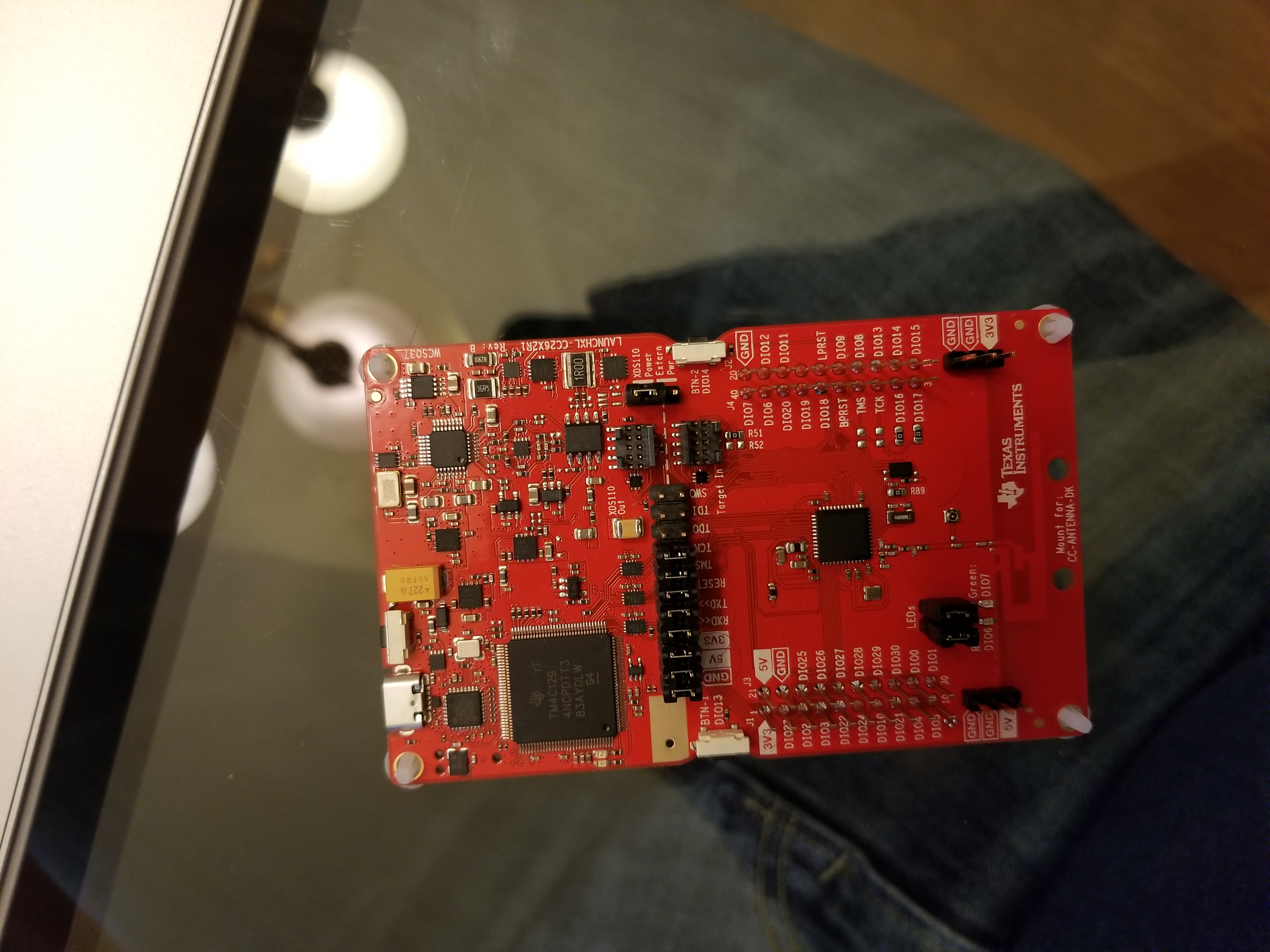
I am using a LAUNCHXL-CC26X2R1 MCU that is branded with CC2642R1/CC2652R1 DEVELOPMENT KIT. 

I am using the IDE environment in CCSV8.3.0.00009

I don't know exactly what the firmware on the MCU is, but when I initially connected it to CCS it upgraded the firmware. 

My problem is that none of the TI Driver examples are working on the MCU. When i send a project to the IDE and run it, it verifies that my MCU is connected, the project builds without errors or warnings and that light next to the CPU blinks red. However, nothing works on the board as promised. I have not hooked an Oscilloscope to the board to test the voltage of the DIO6/7.

I am following the tutorial listed here:

dev.ti.com/.../

What am I doing wrong?

  • Can you see anything output from CC26x2R UART? I am not sure what HW EVB you use. Can you take a picture to show me your HW?
  • Hello Chen,

    Thanks for the reply. I don't know how to see an output from the UART. I haven't done anything like a printf command on this board yet. I was just starting to learn the ins and outs of programming an embedded system for a school project. I am a novice and simply plugged the board in and hit run. If you could help I would be greatly appreciative. 

  • When you connect USB cable between LaunchPad and PC, LaunchPad should emulate two virtual COM ports. You can use any terminal tool like teraterm or Putty to open the one called Application COM port to see if there is any UART message output from the com port.
  • Please try to connect your boards to a PC running SmartRF Studio and confirm that the boards shows up there and work as expected.
  • I added the following lines to empty.c

    #include <stdio.h>

    while (1) {
    sleep(time);
    GPIO_toggle(Board_GPIO_LED0);
    printf("printf ran in a while loop");
    }

    After adding these lines, i opened putty to the serial port connection. I opened device manager and found that UART was on com port 9 . I then set putty to com9. I went back to CCS and loaded the program onto the cc26x2r and after loading with no issues, putty did not report any UART messages. 

  • I downloaded SMARTRF Studio v7 while the MCU was connected. The program registered that a device was connected. I went to the 2.4GHZ tab and clicked cc2652 and a dialogue opeened asking me if i wasnted to test the BLE or the 802.15.4 . I tried once with BLE and once with 802.15.4. Both times I ran all 4 tests and saw varying results happen. However, I am not sure exactly what I am looking for. No error messages popped up, so I assume everything was working fine.

    I could not load a program from CCS to the device while the SMARTRF tool was operating, so I could not test what happened while code was running.

    What should I do next?
  • If you mean to output something from UART, you can refer to UART echo examples at dev.ti.com/.../
  • Since your boards work with SmartRF STudio I would assume that they are OK. You cannot use CCS and SmartRF Studio at the same time, and as YiKai said, if you want to use UART, you should look a UART example. I think it would be a good exercise for you if you take a step back and go through of our tutorials in SimpleLink Academy before you start developing code yourself.

    dev.ti.com/.../

    Siri
  • Thank you Siri, 

    I was able to get my hands on a few different boards that work out of the box. However, I will follow your advice and go through a few different examples to learn what I'm missing. 

    Thank you,

    Craig Edwards