


Part Number: TRF7970A
Hello,
I'm integrating the TRF7970A chip using the Boosterpack sold by DLP Designs. I've used an oscilloscope to verify that commands are sent to the device properly, but I'm running into issues probably related to initialization. Post initialization, whenever I attempt transmitting commands or addresses for register operations I observe the following behavior on the oscilloscope (apologies for the hand sketch, this is only a representation):
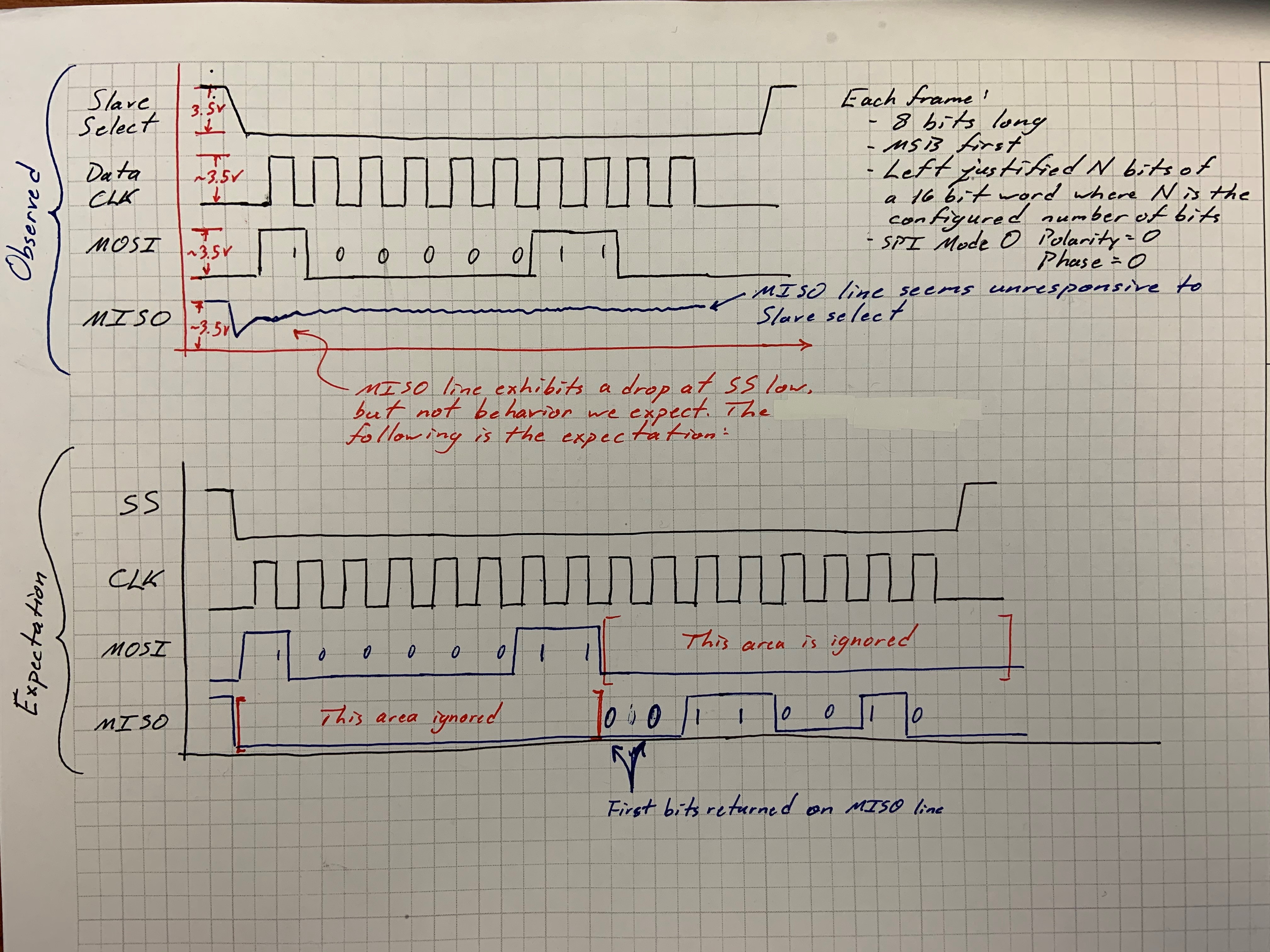
I believe I initialized the NFC module properly by following the procedure in the data sheet on page 49. The following functions initialize the NFC module:
void initializeNfcModule(void)
{
SpiTimerActive = false;
setSpiSlaveSelectHigh();
// Four millisecond delay between bringing SS high and then EN high per TRF7970A Datasheet
DEVICE_DELAY_US(4000);
// Set TRF Enable Pin (EN) High
setEnHigh();
// Wait until TRD system clock starts
DEVICE_DELAY_US(5000);
// TODO: Set up TRF initial settings
TRF7970A_initialSettings();
TRF7970A_setTrfPowerSetting(TRF7970A_3V_FULL_POWER);
}
// Initialize the TRF7970A using commands
void TRF7970A_initialSettings(void)
{
g_ui8CollisionPosition = 0;
g_ui8FifoOffset = 0;
g_ui8FifoRxLength = 0;
g_sTrfStatus = TRF_IDLE;
g_eTrfGeneralSettings.eTrfPowerSetting = TRF7970A_3V_FULL_POWER;
g_eTrfGeneralSettings.bRfFieldOn = false;
g_eTrfGeneralSettings.ui8IsoControl = 0x02; // TRF7970A Default
g_ui8IrqFlag = 0x00;
g_ui8TimeoutFlag = 0x00;
// Send out SOFT_INIT + IDLE initial sequence to soft reset
TRF7970A_sendDirectCommand(TRF7970A_SOFT_INIT_CMD);
DEVICE_DELAY_US(1000);
TRF7970A_sendDirectCommand(TRF7970A_IDLE_CMD);
// Delay to ensure soft reset is processed
DEVICE_DELAY_US(1000);
g_eTrfGeneralSettings.ui8IsoControl = 0x21;
TRF7970A_resetFIFO(); // Reset the FIFO
// Configure the system for ISO14443A cards
TRF7970A_writeRegister(TRF7970A_ISO_CONTROL, 0x08); // For Iso14443a cards
TRF7970A_writeRegister(TRF7970A_MODULATOR_CONTROL, 0x01); // ASK 100%, no SYS_CLK output
TRF7970A_writeRegister(TRF7970A_REGULATOR_CONTROL, 0x01);
TRF7970A_writeRegister(TRF7970A_NFC_TARGET_LEVEL, 0x00); // For TRF7970A Errata
}
Unfortunately all data extracted from the MISO line during communication always returns 0xFF because the MISO line is always high (see above picture).
My question: is there anything wrong with my initialization sequence? I cant see any issues.
-Charlie

