This thread has been locked.

If you have a related question, please click the "Ask a related question" button in the top right corner. The newly created question will be automatically linked to this question.

TRF7960 External Antenna via SMA Port

Other Parts Discussed in Thread: TRF7960, RF-HDT-DVBB

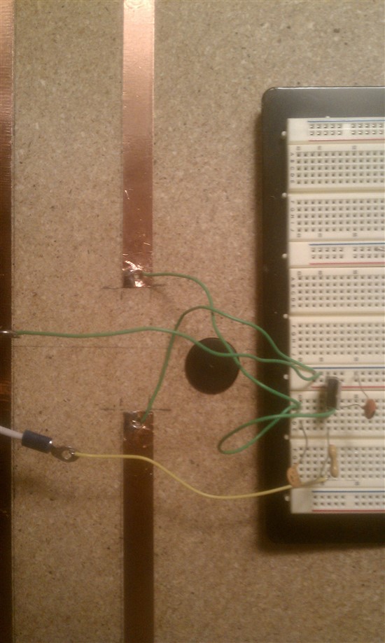
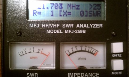
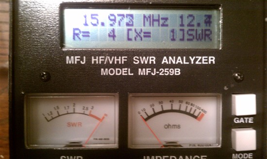
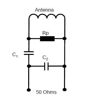
I have built a external antenna following the guidelines of the HF Antenna Cookbook and HF Antenna Design Notes and am trying to connect it to the TRF7960. I can get teh TRF7960 on board antenna to work but can not get any output for the external antenna. I have been searching and have found no one with the same problem. Is there a register or pin I have to set to use the SMA connector instad of the on board antenna. I realize that the antenna still has to be fine tuned but I have no current at the SMA output.

  • Hi Brad,

    If you are using the TRF7960EVM, you should remove R3 to route the signal to the SMA port and disconnect the on board antenna. 

    The TRF7960TB users guide has a section on antenna tuning that is quite useful as well.  If you would like, I can also provide assistance tuning your antenna. 

    http://focus.ti.com/docs/toolsw/folders/print/trf7960tb.html

    Best Regards,

    Eddie LaCost

  • Yes I am using the Evaluation Module. I have removed R3 but still no luck with getting anything at the SMA output. I am running the board through USB but have 5v connected to run the board in 5v mode. Is there anything else I could do to get any power at the output?

    Thanks.

  • There is no need to supply 5V externally to the board.  5V can be supplied from USB. 

    If you connect a scope, do you see any voltage at the SMA without the antenna connected?

    What was your process for tuning the antenna? 

     Best Regards,

    Eddie LaCost

  • That is the problem I am running into; I have nothing at the SMA with or without the antenna connected. This is the first time I have hooked up the board to the computer and the on board antenna works (well worked) great so I don't get why the external antenna is not getting power. I am going to use a mfj antenna analyzer but until I get anything at the TRF7960 output I am not going to start that process.

  • If you did not change any of the other resistors, you should be pushing signal to the SMA.  If R3 is left in the circuit, the power is split between the on board antenna and external antenna.  If R3 is removed, all the signal is sent to the SMA.  Please refer to the EVM schematic and make sure that R4 is populated as well. 

    It could also possibly be that your scope is not set up properly.  Are you able to measure the voltage across the onboard coil?  You should see voltages similar to the attached shots.

    Let me know what you find.

    Best Regards,

    Eddie LaCost 

    TRF796x EVM Oscope TX_RX Screen Captures(3).ppt
  • The scope now looks good with R3 removed. When the MFJ arrives will see how the baseline looks and see if I have any problem there.


    Thanks for the help.

  • Okay now I see where my problem has been, the antenna is resonating at around 27-30Mhz. Using the MJF 259b I measured the inductance at 0.774uH, then calculated the needed capacitance needed to be 177pF (I have a 10-180uH variable cap in the tuning circuit). Adjusting the capacitor I can not get ANY change in the frequency. Is there something else that I am forgetting to do in order to tune this.

  • Brad,

    The antenna tuning will consist of a parallel cap for resonance, a parallel resistor to set the Q, and series cap to match to 50 ohms.  If you measured your coil at 774nH, your complex impendance will be roughly 1 + j65.91 in free space.  This is derived from 2 pi fL.  I have simulated component values using a Smith Chart based on this complex Impedance.  See the attached screenshot.  I have indicated in the screeshot how each componet shifts the plot on the Smith Chart.  This gets you to around 47 ohms which is close enough to start with.  The values I used are:

    Parallel Cap: 120pF

    Parallel Resistor: 1k

    Series Cap: 62pF

    Try these values and see if that gets you closer to 13.56MHz.   

    Best Regards,

    Eddie LaCost

  •  


    Eddie,

    I have placed the components as described and am not getting a resonance frequency of 22Mhz. At 13.56MHz with the tuning circuit attached I have a inductance of 0.494uH. I still do have the 180uF tuning cap and 10Kohm resistor across the 1/2" gap on top of the antenna but I do not believe that that seems to be doing anything. So it is helping out a lot but for some reason something still seems to be off. I did measure the baseline inductance again (this is with the cap and resistor across the gap, not that it matters) and it is still around 0.770uH.

    I did add a 33uF cap in parallel with the 66uF cap which makes the frequency about 16MHz, but still cant pick up any tags with the reader.


    Thanks again.


    Setup with added cap in parallel (below):


    Setup as you described (below):

    With the 33uF cap added in parallel to 62uF cap (below):

  • Brad,

    For this coil, you should do a capacitive match.  The schematic should look like the image below.


     First, remove all components and measure the complex impedance of the coil alone at 13.56MHz.  This is expressed as R + jX.  You can also measure the inductance of the coil alone.  You can then follow the antenna tuning details shown in the TRF7960TB guide(section 13).  If you need assistance, let me know what complex impedance and inductance you measure and I could give you estimated rough tuning values. 

    Also, if your inductance is low, you can make the copper tape trace thinner to increase inductance. 

    TRF7960TB Users Guide: http://www.ti.com/litv/pdf/slou297   

    Best Regards,

    Eddie LaCost

  • I have made a lot of progress and believe I know where to go but and confused on one thing. First I did measure my impedance to be 1+j61.34. Using the formulas specified in the TRF7960TB users guide I calculated Cres=191pF and R=1226ohm == 1.2k. From there I simulated and built the following circuit.

    This circuit was able to get the antenna frequency down to 13.56MHz but but R=1 still (50 needed). I realized your circuit setup in the previous post hinted to building the circuit the following way. The one confusing thing is that you suggest two different circuit layout which greatly change the design. I did simulate the circuit with the parallel capacitor before the series capacitor and came up with the following values. Would this be correct. (I am waiting on different capacitors in order to try this circuit out.) When measuring this layout using (2) 20-180pF caps I can get the impedance to be 4-j0. This seems to be the same response I get when simulating using values of those values with this layout.


  • Brad,

    Sorry for the confusion there.  The series cap should come after the parallel components. 

    Unfortunately, I cannot read the values you used in the Smith Chart plot.  If complex impedence is 1 + j61.34, I see the following values:

    R parallel: 1.2k ohm

    C Parallel: 139pF

    C Series: 56pF

    These values should get you very close to free space tuning.  Keep in mind that the TB board had a complex impedence of 0.8 + j80.8. 

    Give these values a try and let me know how it works out.

    Best Regards,

    Eddie LaCost

  • Using those values (which is what I calculated in the screen shot you could not see) I can get the complex impedance down to 0 but the real is just 4ohms. Now if I use the other values Cp = 794pF  Cs=247.1   Rp=3.2ohm I can get the real impedance to equal 50 but the complex is way off (around 80ohms). Is there some variable I am not thinking of that could be messing with the impedance of the antenna when trying to tune?

  • Brad,

    How are you measuring this with the MFJ259b? 

    First, make sure that your antenna is completely disconnected from the reader circuit.  Connect your antenna with a short coax cable or SMA to SMA connector.  See picture below for a good example.  At this point, you should have the tuning values populated.  Go to the Impedence R & X mode of the MFJ.  Use the tune knob to adjust to ~13.56MHz.  You should now see your impedence and SWR.  In the image below, R = 49 and SWR =1.0.  This antenna is tuned very well.

    If you can also provide a picture of your setup and measurements, that would be helpful.

    Best Regards,

    Eddie LaCost

  • I am using the Tune to Resonance Mode (x=0) under the advanced mode. The following picture are my setup. I am using a somewhat long coax cable but it is the same length that I will be using in the design when finished. As you can see using the calculated cap and resistor values The complex is correct but real impedance is only 4-5ohms. (The other circuits on the breadboard are for different applications.)


  • Thanks for the pictures.  How large is this antenna?  It looks like 1000 x 600 from our app note.  I think this is probably too large for the TRF7960 to drive properly without a power amplifier.  What range are you trying to acheive?  What tag size?  This antenna design is intended for a high power reader.

    To do an unbalanced capacitive match, you should have a loop with matching components parallel and series to the loop.  For your antenna, you could remove the T matching arms and tap the coil on the other end.  Again, this antenna is probably too large for the TRF7960EVM to drive properly.  TRF7960 is just 200mW output power.  You probably need about 1W for the antenna pictured.

    Best Regards,

    Eddie LaCost

  • Okay, I will give that a try. The antenna is 2' x 4'. I did figure I would need a power amp to drive it but figured I'd try and get it tuned first. I do not need really any range out of it, maybe around a inch or so, I just need the large read area.

  • As of right now with the tap moved over to the side with the 1/2" gap I am using the circuit in Figure 28. What that circuit I got 25+0j. I am going to try and play around with it some more and see what I can get. 

    Now as for using 2 matching methods at the same time (unbalanced capacitor matching and T-matching) could that be messing with me a bit? I have not seen any design notes about T-matching but could moving the taps around also help me out?

    I removed the tap all together and just tap into the antenna at the 1/2" at the top (using only cap matching method) and was also able to get 25+0j.

    Thanks again for all your help, Brad.

  • Brad,

    Can you try doing an unbalanced capacitive match as shown in the attached mock up of your photo?  You should measure the antenna complex impedence again to ensure you are getting a similar value before placing components.

    You may need to remove the T arms as well to get an accurate measurement.   

    Best Regards,

    Eddie LaCost 


  • Calculations from HF Design Notes: 

    Antenna Impedance = 1+j60

    Measured Inductance: 0.616 uH

    Measured Capacitance: 169pF


    R par = 2pifLQ = 2 * pi * 13,500,000 * 0.000000616 * 20 == 1K


    C par = C total * sq(Zout/Zin) = 169pF * sq(1000/50) = 756pF


    C series = 1 / [(1/C) – (1/C par)] = 1 / [(1/169) – (1/756)] = 218pF


    With these values the antenna is basically unresponsive staying around 1+1j. I did sim the circuit and the calculations do not seem correct; the capacitance seems way to big.


    Using the values I had before I was still able to get the antenna to around 30+j0. 


  • The following picture IS NOT photoshopped.

    The end resulting circuit was the following the the Tag-It Antenna Design Guide. The know all of the steps have helped along the way but there was one thing I noticed that I was doing wrong that was stupid enough not to say. What you did say is true though; I hooked it up to the reader and launched the windows app and it won't read a tag. Although it does not give any bogus information that it thinks it finds anymore so I would assume it is working. I know I tried to look for one before I bought the 7960 but do you guys make a higher wattage reader or a power amp for the 7960?

    I am using RF-HDT-DVBB - 13.56mHz Overmolded Transponder. The project that I am using this in needs the 2' X 4' read area but only about 6" of read range. The bottom will he shielded and will only read the top side.


    Thanks again, Brad.

  • That looks good. 

    We do have an app note for a 4W power amplifier intended for TRF796x.  See the link below. 

    HF Power Amplifier: http://www.ti.com/litv/zip/sloc132

    For an off the shelf high power reader, I would suggest Feig products.  Their MR101 goes up to 1W and LR2000 goes up to 8W.  Using an antenna this large and fairly small 22mm tag size, 1W may not be enough power.  If the output power is not enough, you may see a "read hole" in the center of the antenna and only read tags in the corners. 

    http://www.feig.de/index.php?option=com_content&task=view&id=71&Itemid=134&lang=en


    Also, be sure that when you add the shield to the bottom, you re tune the antenna with this in place if you have not already. 

    Best Regards,

    Eddie LaCost

  • Ordered the Feig MR101. Am going to hope that 1W is enough to drive the antenna. Read hole would not be optimal but would not be horrible. If that does not work, hopefully not the case, I found this amplifier that was used with S6700 module which looks to be the best second option. http://www.eng.tau.ac.il/~yash/kw-usenix06/kw-usenix06-forhtml-img7.gif.

  • The never ending problem continues. I recieved the MR101 today and got it set up. I do not have it connected to a computer yet but from reading the manual the led should turn red is a tag is present. The antenna is calebrated perfect according the the the 259b yet I can not get any red led from the small transponders, or the big tags that came with the TRF7960. Is it really possible that 1W is not enough to read any tags?

    IS there anything that could cause a huge change in impedance. Now my baseline impedance is 45+82j which is a HUGE jump from 1+62j. Of course it is also detuned now.

  • Brad,

    I have not ever used the MR101 in a stand alone mode like that.  I have always used the PC application, so I am not sure exactly how that mode works.  Have you tested connected to the PC?   

    Environmental change could cause the change in impedance.  If the the shield was not present initially, this may explain it.  That does seem like more of a jump than would be expected from a metal shield under the coil though. 

    Best Regards,

    Eddie LaCost

  • All,

    Even though the impedance match is at 13.56 MHz, it is much better to build a small PCB for the matching network and place the parts close together.  Use good RF matching & layout techniques and the "antenna" inductor impedance match will work the first time.

    Regards,

    Eric Hooker

    RF Consultant

  • have you been success with the big antenna? I am also looking for similar project (from Chennai,TN, India) like an NFC Reader which can read all tags upto 1 meter. Do you have any idea about availability of NFC vicinity readers and tags?
  • Yes it did. The biggest issue was as mentioned above was the large margin of error when using a breadboard. After having a PCB made it was relatively simple to get everything dialed in. I have not dealt with wireless communication since this project so I do not know much about availability of NFC readers/tags.