This thread has been locked.

If you have a related question, please click the "Ask a related question" button in the top right corner. The newly created question will be automatically linked to this question.

TRF7970A: SPI Communication Issues

Part Number: TRF7970A

Hi,

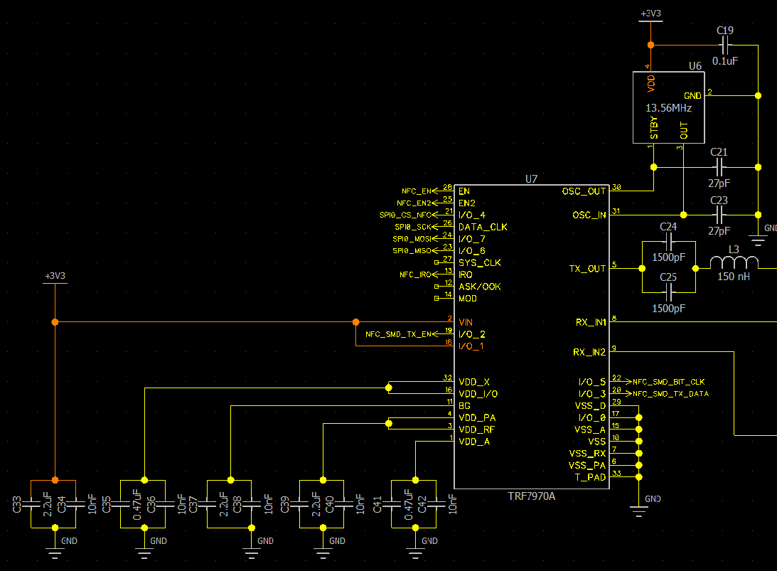
We are developing an nfc reader board using the trf7970A but were having issues communicating with the IC through spi reliably. I send a read status control register after restarting the IC (cycle chip enable) and it takes 2-4 tries for the chip to return the correct value of 0x01. We removed the chip and wired the dlp 7970ABP to the pads and it reliably returns the correct value on the first try. I'm thinking something is wrong with our schematic but I'm not sure what:

  • Hello Sava,

    The root cause is almost certainly the VDD_X capacitor selections. That sounds very much like issues when VDD_X capacitors are omitted or diff notably from schematic. VDD_X needs 2.2uF and 10nF caps for proper device operation. VDD_X is an internal regulator that sources a lot of key device functionality on the digital side so if it is not operating correctly many issues can occur including poor communication as you've seen.

    I'll also mention VDD_A needs 2.2uf and 10nF as well.

  • Hi Ralph,

    Replacing the capacitors seems to have fixed the status control register read unreliability, however we still have issues with other spi commands. After sending the polling cycle sequence command and the IC pulling the IRQ line high, the IRQ status register is always 0x00. When we attach the DLP board to the pads, we reliably read 0x80 (tx is finished).

    Thanks,

    Sava

  • Hello Sava,

    Are you referencing TI example code? If so, which one.

  • Hi Ralph,

    Sorry for the delay but we got a pcb revision done with the decoupling capacitors placed closer to the pin (as well as fix the values). we're communicating using our own firmware developed for the nordic nrf52 chip but based on the TI example code. We're still having issues with certain registers reading 0 even after we set them with a different value. Is there any support beyond the forum we could get for the TRF7970 chip?

    Thanks,

    Sava

  • Hello Sava,

    What SPI mode are you using? There is only one SPI mode supported by the device.

    That supported SPI mode is: Clock Polarity = Low, Data Valid = Falling Edge

    In SPI terms that is CPOL = 0, CPHA = 1, also known as SPI Mode 1.

    Another important piece, what is your SPI clock speed?

    Also what is the process for powering up the device. Is the device being brought up according to Figure 6-3 (with EN2 not being required if it is left grounded)?

    Are the steps in Section 6.11 TRF7970A Initialization being followed?

    What is the result of reading Register 0x0F, are you getting a correct Crystal Stable bit results?

    The forums are the primary support channel for these devices. We try to reply quite promptly whenever possible.

  • Hi Ralph,

    The issue was with our crystal.

    Thanks for the help,

    Sava