This thread has been locked.

If you have a related question, please click the "Ask a related question" button in the top right corner. The newly created question will be automatically linked to this question.

CC2652R: Learning Firmware Coding: I2C codings help

Part Number: CC2652R

Hi TI

I have a mini project here on my own.
Currently I have a lunchpad CC2652R with me. I would like to add a I2C temp/humid sensor for reading.

I been reading a few example codes provided by TI explorer. However being new to this coding, I have a hard time understanding the codes.

Would like to seek your advice and help.

One of the C files i looked at was I2ctmp.C to understand how I2C coding works, however I am still confused.
I understand that I2C, we need to send an address hex followed by a command hex. Not sure about the acknowledgement thing too.

I been trying to solve this. I have tried multi_sensor and Multi_role project too. Still trying to understand how do I write these codings to initiate the process I2C command write and read.

Here is a simple logic I trying to do,

1. CC2652R wake up from sleep.
2. Send command to sensor to wake up, and extract data, temp and humid.
3. Display output on Teraterm.
4. Additional is send a BLE message with this data
5. Sleep both MCU and sensor after BLE message send out.

I think I would like to solve 1-3 first before moving onto the BLE portion.
Any kind soul can explain how do I write these codings for 1-3? 

Here are some photos I tried using I2ctmp.C file. Modifying the address of the first temp sensor.
However I keep receiving no acknowledgement. Also I cut short the sample from 20 to 10 just for easier testing.
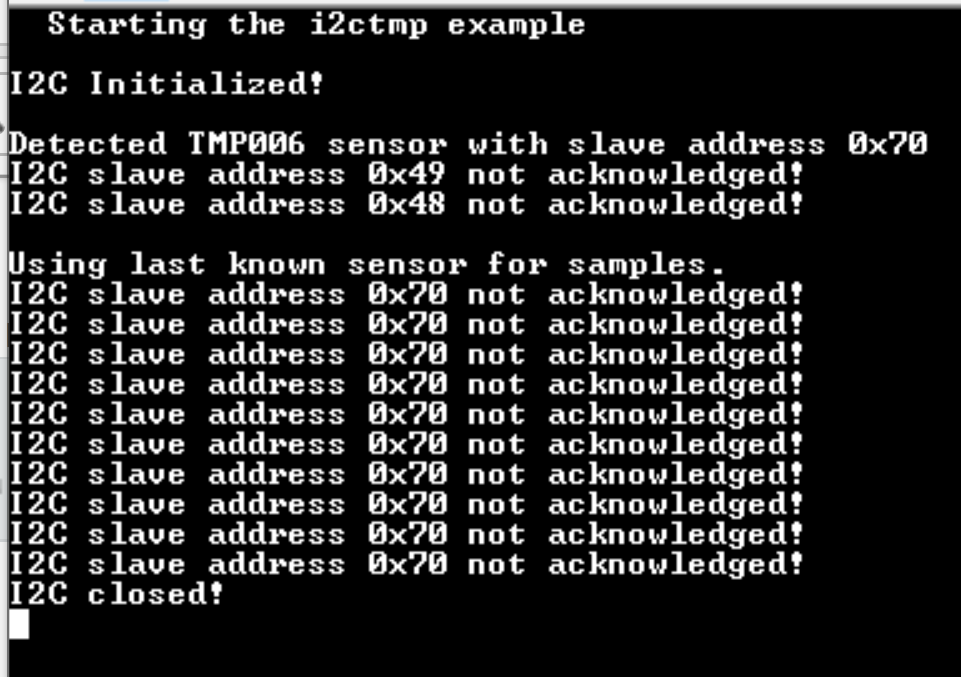
I guess I miss out some part or maybe the example codings is not meant for this sensor. 

I am using a SHTC3 sensor. Where the datasheet stats I have to send a wakeup command and a read command to extract data.
But however, I not sure how do I approach this in terms of the C codings. How do I write such code?

One thing I also had first experience with CCS. How do I start with empty.C? What do I need to do?
I did use Arduino before but they are a simple way of adding library in and call the library for the function.

Would be happy to receive some guidance from some expertise in this forum on how do I do this.
I am really excited to develop this mini project. However, I am a hardware engineer. Had no prior firmware coding experiences.
Please do share your insights and help. Really appreciate it.

Thanks and regards

Dan

  • Hi Dan,

    Could you share datasheet of the sensor and what modifications you did to the code? 

    As your example seems to detect the sensor when probing for it (the "Detected ..." printout) I would assume the sensor is running as it should. In that case, I would guess that the "Not acknowledged" prints is due to you sending a command to the sensor that is not valid (which means it does not ACK you back). You do not need to consider the ACK/NACK yourself, this is happening under the hood and the driver will report back if the sensor responds with a ACK or NACK. The actual way ACK and NACK is used for a specific device could vary but typically a slave ACK all valid data, a NACK is the same as not responding (which could be because there is no sensor or the request was invalid).

  • Hi MW

    Thank you for the reply.

    Attached is the sensor datasheet.

    HT_DS_SHTC3_D1_TempSensor.pdf

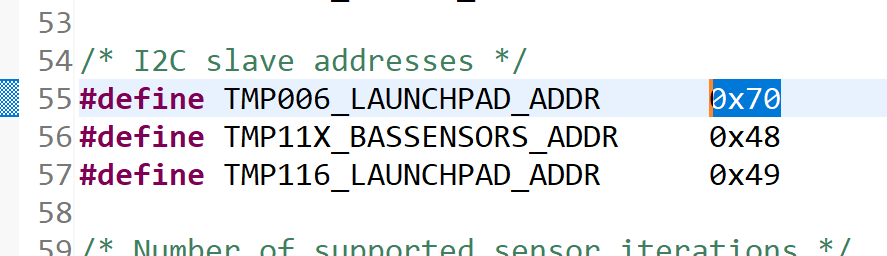
    Currently, I only change the sensor address from the original 0x01 to 0x70

    This is the only changes I made to the codings.
    I been trying to figure out how do I write additional commands to send.

    According to the sensor datasheet, I have to send a wake up command and measure command to the sensor.
    As I read the coding examples. I have no idea where to write or what to write to implement the commands.
    I figure it should be right before the ""retrieve 20 samples line.

    Wakeup: 0x3517
    Measure: 0x7CA2
    Sleep: 0xB098

    How do I send these 3 commands? From the codings I tried to learn

    Is this line correct "i2cTransactions (Wakeup ,measure, sleep);" ?

    Been swimming around TI training page and forum to figure how do I approach this I2C codings.
    I also looked into SCS and I2C designer. Feel kind of lost.
    As most sheets I read are mostly concept of I2C but not much of codings.

    Hope to hear from you soon. 

    Regards
    dan

  • Hi Dan,

    I suggest you look at the driver documentation, it contains examples on read and write operations (or a combo of the two)

    https://dev.ti.com/tirex/explore/node?a=pTTHBmu__3.20.00.68&node=AP24VgJ7gbuZWQrdF16tIg__pTTHBmu__3.20.00.68

    In short, if you for example expect to write 2 bytes and get one back, you would do something like this:

    /* Common I2C transaction setup */
    i2cTransaction.slaveAddress = SENSOR_ADDRESS;
    i2cTransaction.writeBuf   = txBuffer;
    i2cTransaction.writeCount = 4;
    i2cTransaction.readBuf    = rxBuffer;
    i2cTransaction.readCount  = 2;
        
    txBuffer[0] = (WAKEUP >> 8) & 0xFF;
    txBuffer[1] = (WAKEUP & 0xFF);
    txBuffer[2] = (MEASURE >> 8) & 0xFF;
    txBuffer[3] = (MEASURE & 0xFF);
    
    I2C_transfer(i2c, &i2cTransaction)

    Note that I did not actually check in what order you expect to send the commands, high or low byte first :)

    Where "txbuffer" contains the data to write and where "rxBuffer"  is used to read in 1 byte from the device. So if you for example would need to issue "wakeup" followed by a "measure" and then read back 2 byte result, it could look something like:

  • Hi MW

    Oh wow, thank you very much.
    This is what I am looking for, an example library of codings where I can get a reference.

    Thank you for directing the driver link. I will try to look into these and write a fresh empty.c page.
    Hopefully I able to get the MCU and sensors work together with an output on teraform.

    Appreciate the help greatly especially for the hardware me. Haha, excited to try now.

    One more question, is there a missing picture regarding the txbuffer and rxbuffer for the wakeup -> measure?
    I will try to understand the reference and implement.

    Big thanks.
    Dan

  • Hi Daniel, 

    Page 7 in your datasheet is what you are looking for. You need to interface with it in 4 steps:

    1) Wakeup
    
    /* Common I2C transaction setup */
    i2cTransaction.slaveAddress = SENSOR_ADDRESS;
    
    /* Wakeup */
    i2cTransaction.writeBuf   = txBuffer;
    i2cTransaction.writeCount = 2;
    i2cTransaction.readBuf    = rxBuffer;
    i2cTransaction.readCount  = 0;
        
    txBuffer[0] = (WAKEUP >> 8) & 0xFF;
    txBuffer[1] = (WAKEUP & 0xFF);
    
    I2C_transfer(i2c, &i2cTransaction)
    
    2) Measure
    
    i2cTransaction.writeBuf   = txBuffer;
    i2cTransaction.writeCount = 2;
    i2cTransaction.readBuf    = rxBuffer;
    i2cTransaction.readCount  = 0;
        
    txBuffer[0] = (MEASURE >> 8) & 0xFF;
    txBuffer[1] = (MEASURE & 0xFF);
    
    I2C_transfer(i2c, &i2cTransaction)
    
    3) Read, this depends on if you use stretching or not (use stretching if possible, looks easier)
    
    i2cTransaction.writeBuf   = txBuffer;
    i2cTransaction.writeCount = 0;
    i2cTransaction.readBuf    = rxBuffer;
    i2cTransaction.readCount  = 6;
        
    
    I2C_transfer(i2c, &i2cTransaction)
    
    4) Sleep
    
    i2cTransaction.writeBuf   = txBuffer;
    i2cTransaction.writeCount = 2;
    i2cTransaction.readBuf    = rxBuffer;
    i2cTransaction.readCount  = 0;
    
    txBuffer[0] = (SLEEP >> 8) & 0xFF;
    txBuffer[1] = (SLEEP & 0xFF);
    
    I2C_transfer(i2c, &i2cTransaction)

  • Hi MW

    Thank you for your help and guidance, really really appreciate it.

    Here are my codings as below, I had an issue with line 85 

    "../empty.c", line 85: error #167: too few arguments in function call
    "../empty.c", line 85: warning #187-D: dynamic initialization in unreachable code

    /*
     *  ======== empty.c ========
     */
    /* For usleep() */
    #include <unistd.h>
    #include <stdint.h>
    #include <stddef.h>
    /* Driver Header files */
    #include <ti/drivers/GPIO.h>
    #include <ti/drivers/I2C.h>
    // #include <ti/drivers/SPI.h>
    // #include <ti/drivers/UART.h>
    // #include <ti/drivers/Watchdog.h>
    /* Driver configuration */
    #include "ti_drivers_config.h"
    // Define name for an index of an I2C bus
    #define SENSORS 0
    // Define the slave address of device on the SENSORS bus
    #define SENSOR_ADDR 0x70
    /*
     *  ======== mainThread ========
     */
    void *mainThread(void *arg0)
    {
        /* 1 second delay */
        uint32_t time = 1;
        /* Call driver init functions */
        GPIO_init();
        I2C_init();
        // SPI_init();
        // UART_init();
        // Watchdog_init();
        /* Configure the LED pin */
        GPIO_setConfig(CONFIG_GPIO_LED_0, GPIO_CFG_OUT_STD | GPIO_CFG_OUT_LOW);
        /* Turn on user LED */
        GPIO_write(CONFIG_GPIO_LED_0, CONFIG_GPIO_LED_ON);
        while (1) {
            sleep(time);
            GPIO_toggle(CONFIG_GPIO_LED_0);
        }
       
    // Open I2C bus for usage
        I2C_Handle i2cHandle = I2C_open(SENSORS); << Line 85
       
    // Initialize slave address of transaction
        I2C_Transaction i2cTransaction = {0};
        i2cTransaction.slaveAddress = SENSOR_ADDR;
        uint8_t txBuffer[3];
        uint8_t rxBuffer[3];
        txBuffer[0] = 0x00;
        rxBuffer[0] = 0x00;
       
    /* Wakeup */
        i2cTransaction.writeBuf   = txBuffer;
        i2cTransaction.writeCount = 2;
        i2cTransaction.readBuf    = rxBuffer;
        i2cTransaction.readCount  = 0;
        txBuffer[0] = (0x3517 >> 8) & 0xFF;
        txBuffer[1] = (0x3517 & 0xFF);
        I2C_transfer(i2cHandle, &i2cTransaction);
       
    /* Measure */
        i2cTransaction.writeBuf   = txBuffer;
        i2cTransaction.writeCount = 2;
        i2cTransaction.readBuf    = rxBuffer;
        i2cTransaction.readCount  = 0;
        txBuffer[0] = (0x7CA2 >> 8) & 0xFF;
        txBuffer[1] = (0x7CA2 & 0xFF);
        I2C_transfer(i2cHandle, &i2cTransaction);
       
    /* Read */
        i2cTransaction.writeBuf   = txBuffer;
        i2cTransaction.writeCount = 0;
        i2cTransaction.readBuf    = rxBuffer;
        i2cTransaction.readCount  = 6;
        I2C_transfer(i2cHandle, &i2cTransaction);
       
    /* Sleep */
        i2cTransaction.writeBuf   = txBuffer;
        i2cTransaction.writeCount = 2;
        i2cTransaction.readBuf    = rxBuffer;
        i2cTransaction.readCount  = 0;
        txBuffer[0] = (0xB098 >> 8) & 0xFF;
        txBuffer[1] = (0xB098 & 0xFF);
        I2C_transfer(i2cHandle, &i2cTransaction);
       
    // Close I2C
        I2C_close(i2cHandle);
    }
    Do you know what is the issue? Or what I can do to solve this?
    Regards
    Dan
  • Hi Dan,

    Take a look at the API docs that I sent you again, you are expected to pass in a structure defining the operation parameters of the driver as well :)