


Other Parts Discussed in Thread: CC2590,
Hey,
A few weeks back I discovered this chip and wanted to make something out of it, so I started to designing a schematic/pcb, and it arrived last week. I soldered all the components, and I was able to flash the boards using the Ti PurePath Wireless configurator it seems like I did not mess up my schematic since the board is able to connect via USB to the computer and a board configured as master is able to transmit (I was able to see some activity using my hackrf). Now the issue is that I can not get a master board and a slave board to pair with each other.
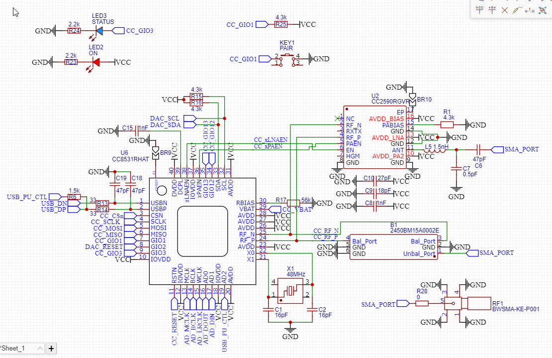
This is likely a configuration issue but after 1 week of searching I couldn't find it, so just in case here are some pictures of the schematic:
(I have foreseen something like this happening, so I added both pads for a matching network and for the CC2590. For this iteration tho the CC2590 is NOT soldered and the same applies for the components related to it. BR9-10 are of course bridged)
But as I said, both boards seems to work fine since each of them is able to transmit while they are in master mode. The status LED also blinks correctly and the chip goes into pairing mode when the button is pressed.
I've also noticed that when I flash each board in master they do not transmit on the same channel.
Is there a way to see what's going on more precisely in the chip that makes it that it don't pair ?
You can find the project files attached, if anybody want's to help I'll take it gladly.
Samuel.
project.zip(project files)

