- Ask a related questionWhat is a related question?A related question is a question created from another question. When the related question is created, it will be automatically linked to the original question.
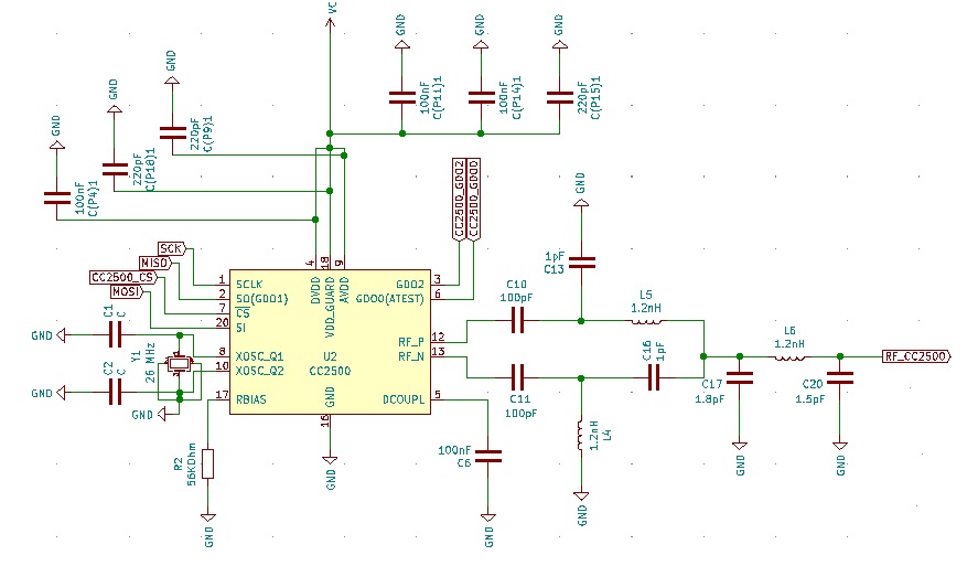
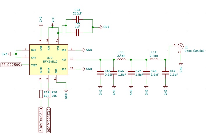
I am planning to use CC2500 along with with RFX2401C (external amplifier) for my transmitter RF Module. For this purpose, I am using pins GDO0 & GDO2 of CC2500 for driving TXEN and RXEN of RFX2401C respectively. And I am using the following code (found on GitHub) to work with this configuration.
void CC2500_SetTxRxMode(uint8_t mode)
{
if(mode == TX_EN)
{
CC2500_WriteReg(CC2500_00_IOCFG2, 0x2F);
CC2500_WriteReg(CC2500_02_IOCFG0, 0x2F | 0x40);
}
else
if (mode == RX_EN)
{
CC2500_WriteReg(CC2500_02_IOCFG0, 0x2F);
CC2500_WriteReg(CC2500_00_IOCFG2, 0x2F | 0x40);
}
else
{
CC2500_WriteReg(CC2500_02_IOCFG0, 0x2F);
CC2500_WriteReg(CC2500_00_IOCFG2, 0x2F);
}
}
I believe the TXEN & RXEN pins are active high. With the changes made to registers from above code, I am expecting GDO0 & GD2 to become high when needed.. Is my understanding correct? Or do I need to make some changes?