This thread has been locked.

If you have a related question, please click the "Ask a related question" button in the top right corner. The newly created question will be automatically linked to this question.

RF430FRL152HEVM: Internal temperature sensor measurenements; how to calibrate

Part Number: RF430FRL152HEVM
Other Parts Discussed in Thread: MSP430G2553

Hi,

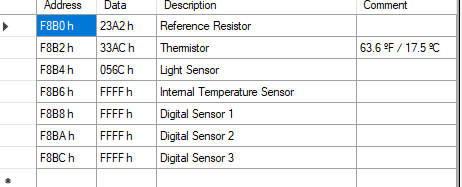
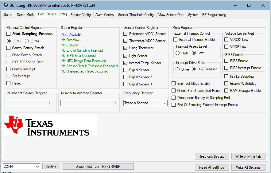
I would like to make some measurements with the the internal temperature sensor in the RF430FRL chip (not the thermistor on the board). Using the windows GUI and the TRF7970ABP + MSP430G2553 reader if I request the Reference resistor (ADC1) thermistor (ADC2) and internal tempterature sensor values in the 'gen. device config.' tab I get the following readout:

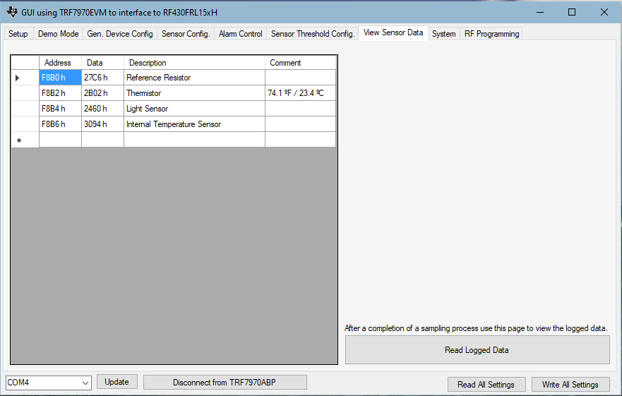
If I request the Reference resistor (ADC1) thermistor (ADC2) and internal tempterature sensor and light sensor values using the windows GUI I get the following readout:

It seems the address for the internal temperature sensor is changing depending on what is selected. In the first instance it was reading the light sensor data address, in the second instance the reading of FFFFh would indicate an error.

Is this the correct way of making a reading from the internal temperature sensor?

Thanks,

Adam.

  • Hello Adam,

    seems the pictures you have copied are missing.

    I have checked that with my setup and got also the 0xFFFF. The problem seems to be the gain setting for the internal temperature sensor which was gain = 2 in my case. When setting gain = 1 I received more meaningful values.

    Best regards,

    Helfried

  • Thanks you for the response Helfried.

    Not sure what happend the pictures.

    What I wanted to show in the pictures was that depending on which sensors I have selected to read data from the address of the internal temperature sensor can change. Am I correct that the address for the internal temperature sensor is F8B6h?

    I can see in the datahseets that's this address is in the range where the sensor data is stored but it is not explicity mentioned as the address for the internal temperature sensor.

    I have tried adjusting gain and the other settings for the internal temperature sensor but can't seem to get a reading other than FFFFh. Note the reference resistor thermistor and light sensor are all reading out value just fine. Can you confirm the settings you are using? 

    I'll try put another screenshot of my readout here:

    Thanks,

    Adam.

  • Hello Adam,

    that is correct that the address is changing in dependence of the number of sensor you have enabled. The firmware is just sampling the enabled sensors and writes the measured data values one after the other into the memory. It is not possible to have fix addresses for specific sensors. In dependence of the number of enabled sensor you create a block of data which will be repeated in the memory when logging over a longer time. So the complete memory can be used for logging data without "holes".

    Please see also the Firmware Users Guide chapter 3 which give examples how the data is stored :

    http://www.ti.com/lit/pdf/slau603b

    For the internal temperature sensor I post here the screenshots of my configuration.

    Best regards,

    Helfried

  • Hi Helfried,

    I have solved the problem. It was my own error I was not pressing 'write settings' after selecting the internal temp sensor to be read from. The device was not receiving any data hence the FFFFh value.

    Your screenshots were very helpful.

    Thanks,

    Adam.