This thread has been locked.

If you have a related question, please click the "Ask a related question" button in the top right corner. The newly created question will be automatically linked to this question.

Programming CC2530 with CC Debugger (No Development Kit)

Other Parts Discussed in Thread: CC2530, CC2530EM, CC1100, CC2500, CC2511, CC2531, CC2530EMK

Hello Everyone:

I'm having some trouble with the CC2530 SoC. Here is the explanation:

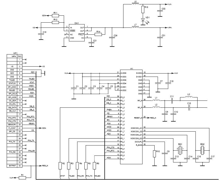
I made my own “Development Kit” by copying the schematic in the datasheet of the cc2530, the application circuit in page 22. I just connect the digital ports and the reset to external pins in order to have access to them and be able to run some tests, the voltage and GND pins are connected as shown in the schematic as well as the other passive components and crystal.

I have the CC Debugger and I connect it to the SoC as the User’s Guide says, I mean I connect the CC Debugger directly to the SoC with no Development Kit,  but the CC debugger is not recognizing the SoC  (The LED In the debugger is RED all the time).

 I read other answers in this same forum and they indicate some solutions like Pull ups resistors and capacitors, I have tried all of them but the CC Debugger is still not recognizing the cc2530.

The question is: Is there any other component or configuration or schematic needed to program the SoC with the CCDebugger.


I will appreciate all the help, because I am kind of stuck.


Thank you

  • You should definitely be able to debug your board with a CC debugger. The connections you need are the following:

    • Pin 1 of CC debugger to GND on your test board
    • Pin 2 on CC debugger to VDD on your test board
    • Pin 3 on CC debugger to DC on your test board, i.e. P2.2 on CC2530
    • Pin 4 on CC debugger to DD on your test board, i.e. P2.1 on CC2530
    • Pin 7 on CC debugger to RESETn on your test board/CC2530

    Note in particular that you need to connect pin 2 to VDD regardless on how you supply power to your test board. This is used by a level converter in the CC debugger to sense the VDD level on your board and convert the debug signals accordingly.

  • By the way, when you say you copied the schematic for the application circuit in the data sheet, I hope that you copied the layout of the RF balun and power supply decoupling from the reference design available at http://focus.ti.com/docs/toolsw/folders/print/cc2530em.html (or another of the reference designs for CC2530). Otherwise you can be almost certain that your RF will not work, or at least have very poor performance. This should not prevent you from debugging the device with the CC Debugger, though.

  • If you don't have external power on your board you also need to connect pin 9 of the CC debugger to VDD.

    Also please note that the application circuit in the datasheet is not the same as the reference design, for CC2530 reference design please visit the CC2530 product page: http://focus.ti.com/docs/prod/folders/print/cc2530.html#referencedesigns

    /delete

  • Normal 0 21 false false false ES-MX X-NONE X-NONE

    Thank you for you answer I didn't expected that quick.

    The connections you describe are the same I have in my board, all are the same but the Reset.

    Here are the connections I have:

    Pin 1 of the CCDebugger to GND

    Pin 2 of the CCDebugger to VDD (3V)

    Pin 3 of the CCDebugger to P2.2 of the CC2530

    Pin 4 of the CCDebugger to P2.1 of the cc2530

    Pin 7 of the CCDebugger to a 2.7k resistor then to the Reset of the CC2530 in parallel to a 1nF capacitor connected to GDN (As the CCdebbuger User’s guide indicates )

    I have a 3V power supply connected to the CC debugger and connected to the CC2530. The Ground Plane is the same for the CCdebbuger and for the CC2530.

    The balun on my board is correct, is the same as the Reference Design, I don’t know about the performance of the RF because I was not capable to test the SoC.

    The debugger is still not recognizing the C2530, now I am adding the decoupling capacitors described in the reference design for the VDD pins. I let you know if it works.

    Thanks again for your answers

  • Hi,

    I just wanted to check if you were able to connect your board to the CC Debugger?

    /delete

  • A schematic of your board would help answer this.  Do you have P2.1, P2.2 with a 10K pull up,  /Reset, gnd and Vcc(debugger pin 2)  connected from your board to the CCDebugger?

  • Hi again. No I couldn't connect the CC Debbuger to the cc2530. I added the decoupling capacitors to Vdd as indicated in the reference design (CC2530EM) and the LED remains in RED. I don't know what else to do.


    thanks

  • yes I tried all of them. Pull-up's , RC filters. here in the forum I read and tried many solutions but none of them worked.

  • Are you pushing the reset button on the CCDebugger to connect?

  • Another question, how much current does the board draw without the cc Debugger attached?.

  • H Stewart said:

    Are you pushing the reset button on the CCDebugger to connect?

    Yes, several times after connecting the board and the ccdebugger

  • H Stewart said:

    Another question, how much current does the board draw without the cc Debugger attached?.

    About 15mA.

    With the ccdebugger abourt 25mA.

  • The current are in the good range.  The interface to the CCDebugger has been gone over several times.  What about the crystall? What part number is it and what type and size caps did you use?

  • H Stewart said:

    The current are in the good range.  The interface to the CCDebugger has been gone over several times.  What about the crystall? What part number is it and what type and size caps did you use?

    I used ceramic capacitors the values are the same of the reference design(CC2530EM), the part number is AVX06035A270JAT2A.

    About the crystal is an Oscilator of 32MHz  by Abracon with part number ABM3B-32.000MHZ-B2-T

    thanks

  • Actually I got ahead of the problem: The CC2530 comes up on the internal RC oscillator, it has to be set up via software to switch to the XTAL.

    If you have access to a o'scope check to see if there are any oscillations on the power supply pins including DECOUPL and watch /RESET while trying to connect.

    If you are away from the o'scope use the multi-meter set on VAC to check the DC lines for oscillation. It should read less than 50mv.

    Use the multi-meter to check the CC2530  /reset pin when pushing  / releasing  the /reset button on the CC_Debugger. Since it is a short pulse when you release the button you will see the voltage drop to maybe 2.8Vdc for a instant. It is easier to see something on the Vac scale where it will be zero in steady state but momentarily show as high as .9 Vac as soon as you release the button.


  • H Stewart said:

    Actually I got ahead of the problem: The CC2530 comes up on the internal RC oscillator, it has to be set up via software to switch to the XTAL.

    If you have access to a o'scope check to see if there are any oscillations on the power supply pins including DECOUPL and watch /RESET while trying to connect.

    If you are away from the o'scope use the multi-meter set on VAC to check the DC lines for oscillation. It should read less than 50mv.

    Use the multi-meter to check the CC2530  /reset pin when pushing  / releasing  the /reset button on the CC_Debugger. Since it is a short pulse when you release the button you will see the voltage drop to maybe 2.8Vdc for a instant. It is easier to see something on the Vac scale where it will be zero in steady state but momentarily show as high as .9 Vac as soon as you release the button.

    Normal 0 21 false false false ES-MX X-NONE X-NONE

    Hi again:

    I just checked the signals you  mentioned and here are the results:

    The reset pin is ok, I was able to see the pulse in the oscilloscope .

    There are no oscillations in the power supply

    There are no oscillations in DECOPL pin


    I also checked the crystal but there are no oscillations, how do you change from the RC internal crystal to the external one???


    Thx again


  •  

    The CC2530 User guide around page 65 at http://focus.ti.com/lit/ug/swru191a/swru191a.pdf has the best description of the clock registers and their settings.

    The CC2530 powers up with the internal 16MHz RC oscillator, you will not see any activity at the crystal.  Once you get the programmer to work the steps to switch to the crystal are summarized in the following:

    1.)   Turn on the crystal oscillator // CLKCONCMD bit 6 set low

    2.)   Wait while  CLKCONSTA.OSC = ! CLKCONCMD.OSC for the crystal osc  to become stable


    Please see the following note and others for other important conditions.


    “Note also that the debugger cannot be used with a divided system clock. When running the debugger, the value of CLKCONCMD.CLKSPD should be set to 000 when CLKCONCMD.OSC = 0 or to 001 when CLKCONCMD.OSC = 1.”


    See software examples for code snippets.


  • Until now I was not able to get to work the programmer. I checked the Reset signal and the noise in the supply.

    The pulses in Reset are correct, and the noise in the supply is not big enough.

    but the LED in the programmer remains in RED with means the chip is not being detected by the programmer.

    Any other idea???

  • We have checked everything including Vcc on pin2.  If you can send me a schematic via "conversations" we can solve this quickly.

  • H Stewart said:

    We have checked everything including Vcc on pin2.  If you can send me a schematic via "conversations" we can solve this quickly.


    Here is the schematic of my evaluation board:

    0820.zigbee.pdf


    Here is the schematic for the conection with the ccdebbuger

    7853.con_prog.pdf


    thx for your help

  • Hi,

    Your design seems to be connected correctly.

    Have you tested your debugger with another device, could you have reprogrammed the firmware on the debugger?

    /delete

  • delete said:

    Hi,

    Your design seems to be connected correctly.

    Have you tested your debugger with another device, could you have reprogrammed the firmware on the debugger?

    /delete

    Hi again:

    the answer is no for both questions.

    I made two boards with the same design and none of them work. I don't have other device for testing the cc debugger. About the  firmware I have not tried yet, let me try and I let you know


    thx for your help


  • The schematic look good but having taken a second look the overal schematic shows pin 41 for the back side chip pad. The second schematic for the debug interface does not show this pin. I realize it may be hidden. Is the back side pad connected to ground?

  • H Stewart said:

    The schematic look good but having taken a second look the overal schematic shows pin 41 for the back side chip pad. The second schematic for the debug interface does not show this pin. I realize it may be hidden. Is the back side pad connected to ground?

    Yes the GND pad of the SoC is connected to the GDN plane in the board

  • I am wondering is this issue was ever resolved?  I have a custom board with a CC2530 that is not connecting to the CC Debugger.  I am using a 2531 dongle to verify that debugger is functional and also to derive comparison waveforms.

  • Hi everybody.

    I have the same problem as Michael described - CC Debugger doesn't detect CC2530 (128k) on my board. The debugger is functional and works with 2530DK and 2531 dongle pretty well. All the connections of debug interface between debugger and my board are taken from appnotes (subject to self-supply of the board - the pin2 is connected, pin 9 is unconnected; at the moment no external pull-ups or RC filters on Reset). I use the latest version of SmartRF Studio and SmartRF Flash Programmer taken from TI site. Has anybody had such a problem? Any ideas are welcome...


    Regards,

    Ilya

  • Ilya,

    Our problem resolved to an incorrect connection to RBIAS (Pin 30).  The hardware guys believed it was unnecessary to connect anything based upon reading the guides, however, to get the internal supplies to run properly, we verified that you need the 56k to gnd.  Once we added this resistor the chip started responding correctly to the CC Debugger.  We did not need any additional interface filtering, etc, and we also did not connect pin 9, as the design was self-supplied from battery.  We actually prototyped a simple PCB to just pinout the CC2530 to figure this out.   What we saw on the scope was good signaling for the reset/clock/data when driven by the debugger, but the response data from the processor was not properly formed.  This lead us to suspect the processor was not actually participating, and review the reasons it might not be. 


    Good Luck.

    Michael

  • Michael,

    I'm glad you manage to resolve your problem.

    Ilya,

    please provide schematics of your set up and I’ll see if I can spot something that could cause the strange behavior.

    /delete

  • Michael, thanks a lot for the reply.

    Unfortunately, your solution cannot be apply in my case as Rbias=56k 1%  has been installed already.

    Delete, below is the schematic of my board in part of CC2530 (A1). CCdebugger is connected to the header XP1 via the simple cable adapter. It uses such lines as debug data, debug clock, Vdd and Reset. The supply of CC2530 is VLA=3V and the same voltage (but from the different source) is connected to pin2 of CCdebugger.


    Regards,

    Ilya


  • Michael, thank you one more time for the promting.

    I've solved the problem. It was concerned with schematic error in my board.


    Regards,

    Ilya

  • Hi!
    I connected my CC Debugger at PC with RF Studio. Could I connect a board with only a CC1100 to the CC debugger and the RFStudio recognize it? Or I need unfailingly a microcontroler interface between the CCDebugger and the CC1100.

    Thanks in advance.

    Sergio.

  • Hello Sergio,

    You should be able to connect the CC1100 to the Debugger.  The CCDebugger contains the CC2500 chip that can interface with the CC1100 through SPI.

    Thanks,

  • It contains the CC2511 which is a SoC with USB, not the CC2500 which is a trasceiver only. I'm guessing it was only a typo on your side.

    Thanks for all your help on the forums Greenja!

    Cheers,

    Fredrik

  • Hello everyone,

    I have a CC2530EM board anc a cc debugger. I'm going to try to program the cc2530 using the debugger with no use of the SoC-BB board at the moment.

    Is the minimum connection for debugging (page 8 CC debugger User guide, according to the pin pattern on page 14 of CC2530 DK User's guide) enough to program, or is it just for debug activities?

    apologize if it a stupid question, I'm fresh with that.

  • All you need to program, and debug, is: Debug Data, Debug Clock, Reset, GND and VDD_sense.

    Cheers,

    Fredrik

  • Hello all,

    I made the connection as suggested by the CC debugger guide, according with the schematic on the CC2530 development kist guide, but CC debugger does not recongnize the cc board.
    I'm supplying the board using the pin 9 of the debugger, is that correct?

    Regards,

    Filippo

  • Yes, you can supply the target from pin 9 of the debugger. Did you remember to connect pin 2 as well (the voltage sense pin)?

  • pin2 should be connected to pin9, or should i use an external supplier?

    thanks for your fast reply

  • You can connect pin 2 to pin 9 if (and only if) you supply your target board from the debugger.

    If you supply power from an external supply to your target, disconnect pin 9, but keep pin 2 connected to the target so that the debugger detects the correct voltage level.

  • I'm supplying by using the debugger.

    Using the development kit, should I use the pull up resistor and the RC filter on the reset pin?

  • Yes, that is recommended.

  • \\red VCC, brown GND, yellow reset, orange DC, green DD

    I follow all the steps as discussed, but still I cannot figure out which problem is. Do you see any mistake there?

  • The link you provided does not work (apparently requires a google account?). Can you attach the schematic or picture (preferably both) directly in this thread?

  • Thanks for your support and sorry for the link I haven't my own schematic yet, I'm working on the bradboard at this stage.

    Here's the picture.

  • A bit difficult to see how you've connected from the picture. Here's an illustration showing how to connect to the EM (looking at the EM from the reverse side):

    By the way, I recommend that you get a SOC-BB (System-on-Chip Battery Board) when working with EMs.

  • it works now! debugger is green!

    I just clean up form all the connection I don't need. I guess I did some mistaken in the connections.

    Many thanks!

  • Hello,

    Is it possbile to use the Zstack demo sensor with the CC debugger and the cc2531 usb dongle?

    I cannot see the communication port on my windows device manager.

    I set the 2 cc2530emk one as coordinator and one as end device, but i cannot run the zigbee monitor tool

    Regards,

    Filippo

  • No, the demo is written for SmartRF05EB and CC2530EM. You would need to add USB CDC functionality to the demo to get the com port up and running on the dongle.

  • thanks for the fast reply.

    How can I do that?

  • You can take a look at the USB firmware library www.ti.com/lit/zip/swrc088. There might also be some explanations of this somewhere in the ZigBee stack documentation (you can post a new question related to this on the ZigBee forum).