This thread has been locked.

If you have a related question, please click the "Ask a related question" button in the top right corner. The newly created question will be automatically linked to this question.

CC1120: CC1120 synchronous serial mode TX & RX

Part Number: CC1120
Other Parts Discussed in Thread: CC1020,

Hello again TI community,

I come back to you with my project of developing a CC1120 RF module compatible with the CC1020 RF module.
here is a brief overview:
The main purpose is to replace our old brand working on CC1020 :

MCU - [CC1020]  <------air-------> [CC1020] - MCU

with a new product based on the CC1120 but software compatible (software in MCU can't be alterated) :

MCU - [MCUb-CC1120] <----air-----> [CC1120-MCUb] - MCU

In my previous post (around 2 month ago CC1120EMK-420-470: CC1120 - synchronous mode - SMARTRFTRXEBK), I asked some help about hardware configuration.
I found out why it didn't work, it was a quartz deviation. I had to reprogram a new frequency to compensate the deviation.

This time I need your help about the "functionality". The CC1120 is programmed in synchronous serial mode with no sync/preamble detection/generation so i have my clock always running.
I have a main transmitter and a main receiver. We have 2 type of communications (for my testing the transmitter send a message every 100ms) :
- 1 way :     transmitter --> receiver
- 2 way :                          -->
                   transmitter       receiver (send response after each valid reception)
                                       <--
                        
I have a LED on the receiver side which change state every valid message received.

With the "1 way mode", the LED change state every 100ms with (indicate  no data loss)
With the "2 way mode", the LED change state but is not stable (indicate data loss)

My question is :
- is strobing RX and TX is enough to correctly switch to their respective mode ? Do I need to reprogram other registers ?

You will find in attached the configuration code and my main (simplified) program.

If you need complementary informations dont hesitate.

Best Regards

Charles

/***************************************************************
 *  SmartRF Studio(tm) Export
 *
 *  Radio register settings specifed with C-code
 *  compatible #define statements.
 *
 *  RF device: CC1120
 *
 ***************************************************************/

#ifndef SMARTRF_CC1120_H
#define SMARTRF_CC1120_H

#define SMARTRF_RADIO_CC1120
#define SMARTRF_SETTING_IOCFG3             0xB0
#define SMARTRF_SETTING_IOCFG2             0x08
#define SMARTRF_SETTING_IOCFG1             0xB0
#define SMARTRF_SETTING_IOCFG0             0x09
#define SMARTRF_SETTING_SYNC3              0xAA
#define SMARTRF_SETTING_SYNC2              0xAA//0xD3  /**///TX
#define SMARTRF_SETTING_SYNC1              0xAA//0x91  /**///
#define SMARTRF_SETTING_SYNC0              0xAA//0xDA  /**///
#define SMARTRF_SETTING_SYNC_CFG1          0x1F//0x0B  /**///
#define SMARTRF_SETTING_SYNC_CFG0          0x03
#define SMARTRF_SETTING_DEVIATION_M        0x7F//0xA0
#define SMARTRF_SETTING_MODCFG_DEV_E       0x03//0x04
#define SMARTRF_SETTING_DCFILT_CFG         0x1C
#define SMARTRF_SETTING_PREAMBLE_CFG1      0x00
#define SMARTRF_SETTING_PREAMBLE_CFG0      0x2A
#define SMARTRF_SETTING_FREQ_IF_CFG        0x40
#define SMARTRF_SETTING_IQIC               0xC6
#define SMARTRF_SETTING_CHAN_BW            0x08
#define SMARTRF_SETTING_MDMCFG1            0x06
#define SMARTRF_SETTING_MDMCFG0            0x0A//0x05 /**/// 05 TX
#define SMARTRF_SETTING_SYMBOL_RATE2       0x73
#define SMARTRF_SETTING_SYMBOL_RATE1       0xA9
#define SMARTRF_SETTING_SYMBOL_RATE0       0x2A
#define SMARTRF_SETTING_AGC_REF            0x20
#define SMARTRF_SETTING_AGC_CS_THR         0x19
#define SMARTRF_SETTING_AGC_GAIN_ADJUST    0x00
#define SMARTRF_SETTING_AGC_CFG3           0x91
#define SMARTRF_SETTING_AGC_CFG2           0x20
#define SMARTRF_SETTING_AGC_CFG1           0x0A//0xAA /**/// AA in TX Freeze both AGC and RSSi update
#define SMARTRF_SETTING_AGC_CFG0           0xCF
#define SMARTRF_SETTING_FIFO_CFG           0x00
#define SMARTRF_SETTING_DEV_ADDR           0x00
#define SMARTRF_SETTING_SETTLING_CFG       0x03
#define SMARTRF_SETTING_FS_CFG             0x14
#define SMARTRF_SETTING_WOR_CFG1           0x08
#define SMARTRF_SETTING_WOR_CFG0           0x21
#define SMARTRF_SETTING_WOR_EVENT0_MSB     0x00
#define SMARTRF_SETTING_WOR_EVENT0_LSB     0x00
#define SMARTRF_SETTING_PKT_CFG2           0x01
#define SMARTRF_SETTING_PKT_CFG1           0x00
#define SMARTRF_SETTING_PKT_CFG0           0x20
#define SMARTRF_SETTING_RFEND_CFG1         0x0F
#define SMARTRF_SETTING_RFEND_CFG0         0x00
#define SMARTRF_SETTING_PA_CFG2            0x7F
#define SMARTRF_SETTING_PA_CFG1            0x56
#define SMARTRF_SETTING_PA_CFG0            0x7D
#define SMARTRF_SETTING_PKT_LEN            0x03
#define SMARTRF_SETTING_IF_MIX_CFG         0x00
#define SMARTRF_SETTING_FREQOFF_CFG        0x22
#define SMARTRF_SETTING_TOC_CFG            0x0B
#define SMARTRF_SETTING_MARC_SPARE         0x00
#define SMARTRF_SETTING_ECG_CFG            0x00
#define SMARTRF_SETTING_CFM_DATA_CFG       0x00
#define SMARTRF_SETTING_EXT_CTRL           0x01
#define SMARTRF_SETTING_RCCAL_FINE         0x00
#define SMARTRF_SETTING_RCCAL_COARSE       0x00
#define SMARTRF_SETTING_RCCAL_OFFSET       0x00
#define SMARTRF_SETTING_FREQOFF1           0x00
#define SMARTRF_SETTING_FREQOFF0           0x00
#define SMARTRF_SETTING_FREQ2              0x6C
#define SMARTRF_SETTING_FREQ1              0xAA//0xAB//0x46
#define SMARTRF_SETTING_FREQ0              0xB0//0x33//0x66
#define SMARTRF_SETTING_IF_ADC2            0x02
#define SMARTRF_SETTING_IF_ADC1            0xA6
#define SMARTRF_SETTING_IF_ADC0            0x04
#define SMARTRF_SETTING_FS_DIG1            0x00
#define SMARTRF_SETTING_FS_DIG0            0x5F
#define SMARTRF_SETTING_FS_CAL3            0x00
#define SMARTRF_SETTING_FS_CAL2            0x20
#define SMARTRF_SETTING_FS_CAL1            0x40
#define SMARTRF_SETTING_FS_CAL0            0x0E
#define SMARTRF_SETTING_FS_CHP             0x28
#define SMARTRF_SETTING_FS_DIVTWO          0x03
#define SMARTRF_SETTING_FS_DSM1            0x00
#define SMARTRF_SETTING_FS_DSM0            0x33
#define SMARTRF_SETTING_FS_DVC1            0xFF
#define SMARTRF_SETTING_FS_DVC0            0x17
#define SMARTRF_SETTING_FS_LBI             0x00
#define SMARTRF_SETTING_FS_PFD             0x50
#define SMARTRF_SETTING_FS_PRE             0x6E
#define SMARTRF_SETTING_FS_REG_DIV_CML     0x14
#define SMARTRF_SETTING_FS_SPARE           0xAC
#define SMARTRF_SETTING_FS_VCO4            0x14
#define SMARTRF_SETTING_FS_VCO3            0x00
#define SMARTRF_SETTING_FS_VCO2            0x00
#define SMARTRF_SETTING_FS_VCO1            0x00
#define SMARTRF_SETTING_FS_VCO0            0xB4
#define SMARTRF_SETTING_GBIAS6             0x00
#define SMARTRF_SETTING_GBIAS5             0x02
#define SMARTRF_SETTING_GBIAS4             0x00
#define SMARTRF_SETTING_GBIAS3             0x00
#define SMARTRF_SETTING_GBIAS2             0x10
#define SMARTRF_SETTING_GBIAS1             0x00
#define SMARTRF_SETTING_GBIAS0             0x00
#define SMARTRF_SETTING_IFAMP              0x01
#define SMARTRF_SETTING_LNA                0x01
#define SMARTRF_SETTING_RXMIX              0x01
#define SMARTRF_SETTING_XOSC5              0x0E
#define SMARTRF_SETTING_XOSC4              0xA0
#define SMARTRF_SETTING_XOSC3              0x03
#define SMARTRF_SETTING_XOSC2              0x04
#define SMARTRF_SETTING_XOSC1              0x03
#define SMARTRF_SETTING_XOSC0              0x00
#define SMARTRF_SETTING_ANALOG_SPARE       0x00
#define SMARTRF_SETTING_PA_CFG3            0x00
#define SMARTRF_SETTING_WOR_TIME1          0x00
#define SMARTRF_SETTING_WOR_TIME0          0x00
#define SMARTRF_SETTING_WOR_CAPTURE1       0x00
#define SMARTRF_SETTING_WOR_CAPTURE0       0x00
#define SMARTRF_SETTING_BIST               0x00
#define SMARTRF_SETTING_DCFILTOFFSET_I1    0x00
#define SMARTRF_SETTING_DCFILTOFFSET_I0    0x00
#define SMARTRF_SETTING_DCFILTOFFSET_Q1    0x00
#define SMARTRF_SETTING_DCFILTOFFSET_Q0    0x00
#define SMARTRF_SETTING_IQIE_I1            0x00
#define SMARTRF_SETTING_IQIE_I0            0x00
#define SMARTRF_SETTING_IQIE_Q1            0x00
#define SMARTRF_SETTING_IQIE_Q0            0x00
#define SMARTRF_SETTING_RSSI1              0x80
#define SMARTRF_SETTING_RSSI0              0x00
#define SMARTRF_SETTING_MARCSTATE          0x41
#define SMARTRF_SETTING_LQI_VAL            0x00
#define SMARTRF_SETTING_PQT_SYNC_ERR       0xFF
#define SMARTRF_SETTING_DEM_STATUS         0x00
#define SMARTRF_SETTING_FREQOFF_EST1       0x00
#define SMARTRF_SETTING_FREQOFF_EST0       0x00
#define SMARTRF_SETTING_AGC_GAIN3          0x00
#define SMARTRF_SETTING_AGC_GAIN2          0xD1
#define SMARTRF_SETTING_AGC_GAIN1          0x00
#define SMARTRF_SETTING_AGC_GAIN0          0x3F
#define SMARTRF_SETTING_CFM_RX_DATA_OUT    0x00
#define SMARTRF_SETTING_CFM_TX_DATA_IN     0x00
#define SMARTRF_SETTING_ASK_SOFT_RX_DATA   0x30
#define SMARTRF_SETTING_RNDGEN             0x7F
#define SMARTRF_SETTING_MAGN2              0x00
#define SMARTRF_SETTING_MAGN1              0x00
#define SMARTRF_SETTING_MAGN0              0x00
#define SMARTRF_SETTING_ANG1               0x00
#define SMARTRF_SETTING_ANG0               0x00
#define SMARTRF_SETTING_CHFILT_I2          0x08
#define SMARTRF_SETTING_CHFILT_I1          0x00
#define SMARTRF_SETTING_CHFILT_I0          0x00
#define SMARTRF_SETTING_CHFILT_Q2          0x00
#define SMARTRF_SETTING_CHFILT_Q1          0x00
#define SMARTRF_SETTING_CHFILT_Q0          0x00
#define SMARTRF_SETTING_GPIO_STATUS        0x00
#define SMARTRF_SETTING_FSCAL_CTRL         0x01
#define SMARTRF_SETTING_PHASE_ADJUST       0x00
#define SMARTRF_SETTING_PARTNUMBER         0x48
#define SMARTRF_SETTING_PARTVERSION        0x21
#define SMARTRF_SETTING_SERIAL_STATUS      0x08
#define SMARTRF_SETTING_MODEM_STATUS1      0x10
#define SMARTRF_SETTING_MODEM_STATUS0      0x00
#define SMARTRF_SETTING_MARC_STATUS1       0x00
#define SMARTRF_SETTING_MARC_STATUS0       0x00
#define SMARTRF_SETTING_PA_IFAMP_TEST      0x00
#define SMARTRF_SETTING_FSRF_TEST          0x00
#define SMARTRF_SETTING_PRE_TEST           0x00
#define SMARTRF_SETTING_PRE_OVR            0x00
#define SMARTRF_SETTING_ADC_TEST           0x00
#define SMARTRF_SETTING_DVC_TEST           0x0B
#define SMARTRF_SETTING_ATEST              0x40
#define SMARTRF_SETTING_ATEST_LVDS         0x00
#define SMARTRF_SETTING_ATEST_MODE         0x00
#define SMARTRF_SETTING_XOSC_TEST1         0x3C
#define SMARTRF_SETTING_XOSC_TEST0         0x00
#define SMARTRF_SETTING_RXFIRST            0x00
#define SMARTRF_SETTING_TXFIRST            0x00
#define SMARTRF_SETTING_RXLAST             0x00
#define SMARTRF_SETTING_TXLAST             0x00
#define SMARTRF_SETTING_NUM_TXBYTES        0x00
#define SMARTRF_SETTING_NUM_RXBYTES        0x00
#define SMARTRF_SETTING_FIFO_NUM_TXBYTES   0x0F
#define SMARTRF_SETTING_FIFO_NUM_RXBYTES   0x00

#endif

while(1){
	if(End_Send){													/* response sent */
		End_Send=0;
		switch(Config[HF_MODE]){									
			case 0x00:{												/*1way*/
				//ret_fct = (unsigned char)(SetupCC1020RX(HF[0x17],0x00U));		/*CC1020*/
				Write_StrobeRegister(CC112X_SRX); 								/*CC1120*/
				What_Do_Hf=Receive_Mode;							/*receive in interrupt*/
				EX0=1;												/*enable interrupt for receiving*/
				break;
			}
			case 0x01:{												/*2way*/
				What_Do_Hf=Receive_Mode;							/*receive in interrupt*/
				//ret_fct = (unsigned char)(SetupCC1020RX(HF[0x17],0x00U));		/*CC1020*/
				Write_StrobeRegister(CC112X_SRX); 								/*CC1120*/
				EX0=1;												/*enable interrupt for receiving*/
				break;
			}
			default:{										   		/*do nothing*/
				break;
			}
		}
	}
	if(End_Receive){												/*Message received*/
		End_Receive=0;											
		EX0=0;
		switch(Config[HF_MODE]){									
			case 0x00:{												/*1way*/
				What_Do_Hf=Receive_Mode;							/*receive in interrupt*/
				Write_StrobeRegister(CC112X_SRX); 					/*CC1120*/
				EX0=1;												/*enable interrupt for receiving*/
				break;
			}
			case 0x01:{												/*2way*/
				/* coding response */

				What_Do_Hf=Transmit_Mode;							/*transmit in interrupt*/			
				//ret_fct = (unsigned char)(SetupCC1020TX(HF[0x17],0xFFU));		/*CC1020*/
				Write_StrobeRegister(CC112X_STX); 								/*CC1120*/
				pos_bit=0U;											
				EX0=1;												/*enable interrupt for transmitting*/
				break;
			}
			default:{										   		/*do nothing*/
				break;
			}
		}
	}
	if(MESS_READY){													/*correct address received*/
		for(i=0U;i!=NBRE_BYTE_IN;i++){								/*copy dans variable de travail*/
			data_all[i]=data_in_tmp[i];
			data_in_tmp[i]=0xF0U;
		}
		MESS_READY=0U;												/*clear flag*/

		if((crc_tmp==0x00U)&&(count_start==count_start_mini)){		/*CRC ok*/
			/* decoding message */			
			LED^=1;
			for(i=0U;i!=NBRE_BYTE_IN;i++){							/*reset variable travail*/
				data_all[i]=0xFBU;
			}
		}
	}
}

  • It should not be necessary to reprogram any register when changing mode between RX and TX. When generating settings, you should use SmartRF Studio and cont. RX, and then use the same registers for both RX and TX.

    Siri

  • Hi Siri,

    That's what I thought and I did like that. Do you have ideas how i can troubleshoot my issue ?

    Thanks for your response

    Best Regards

    Charles

  • What is the issue you have? In your first post you simply state that you are using the CC1120 in serial mode, and you ask if you can use the same registers in RX and TX.

    Siri

  • Hi,

    I'm experiencing data loss when i toggle the HF mode (switching from RX to TX or TX to RX)

    In "1 way" mode, I program the register once at start then never again (module stay in RX) and i have perfect reception (1 "serial packet" every 100ms)

    In "2 way" mode, I program the register at start then I switch the module to TX after a "serial packet" received. Once I have transmitted a certain amount of bits, I switch the module back to RX. In this mode i see that i loose some RX packet.

    EDIT

    I made the following tests (in "1way" mode) :

    - acces to a register (RSSI1) after each message received --> no data loss

    - strobe "RX" after each message received (which is not usefull since the module is programmed in RX) --> start to loose some data

    - strobe "SNOP" after each message received --> no data loss.

    I transmit 13bytes of data, 3 bytes of preamble (AA-AA-AA) and 3 bytes of sync (D3-91-DA).The duration to transmit the data is around 15ms. With a delay of 100ms between each transmission i shouldnt loose any data.

  • I tested the serial example from here:

    https://www.ti.com/lit/zip/swrc253

    and modified it to do TX between every received packet, and I did not experience any packet loss due to inserting the TX there.

    As I do not have the same HW or SW that you have, it is not possible for me to know what is causing your problems.

    I would strongly recommend that you take use recommended settings from SMartRF Studio (RX Settings) and start by testing known good SW. You should also start by using a CC1120 as the transmitter (using SmartRF Studio). Once you have confirmed that everything works as expected you can move on to replace the transmitter with a CC1020.

    If you start seeing problems now, we know that the problems is related to the CC1020, CC1120 communication and not with the SW.

    BR

    Siri

  • Thanks for your support Siri,

    I ll try your suggestions and I ll be back to you with the results

  • Hello,

    I'm back with some results but unfortunatly no good news.

    "I would strongly recommend that you take use recommended settings from SMartRF Studio (RX Settings)" That's what I did since the start.

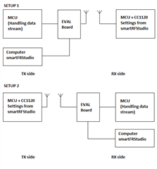
    I ran test with 2 CC1120 modules like this setup (both in synchronous serial mode - blind mode):

    Since I had the same issue (loosing data on the RX side). I switch 1 side with the evaluation board like the following:

    In setup 1 :

    - test 1 : evaluation board lock in TX with smartRFStudio and MCU + CC1120 stay in RX --> OK

    - test 2 : evaluation board lock in TX with smartRFStudio and MCU + CC1120 respond after each reception --> NOT OK

    In setup 2 :

    - test 1 : MCU + CC1120 stay in TX and evaluation board stay in RX with smartRFStudio --> OK

    - test 2 : MCU + CC1120 goes in RX (I also test in IDLE, same results) after each message sent and evaluation board stay in RX with smartRFStudio --> NOT OK

    Since you don't have any issue like mine in your test, I need to test with 2 evaluations board but then how can i edit the code so the evaluation board (on the rx side) switch to tx after a message have been received then switch back to rx right after the end of the transmission.

    EDIT :

    while in setup 2 I have the RSSI plot on the smartRFStudio (continuous RX), In test 1 my RSSI stay high since the TX module is permanently in TX mode. In test 2 I see spike of RSSI (1 each 100ms) but sometimes the spikes have a "bad shape" (cut in 2 spikes, shorter one,...) maybe it's related to my issue ? Or it's just a visual bug ?

    Best Regards

    Charles

  • I think that the only way we can make any progress here is if you can reproduce the issues you are seeing on our HW so that I can reproduce it here.

    Since the problems are on the RX side, you could use SmartRF Studio + TRXEB w/CC1120 on the transmitter side. You should not to use a separate MCU in addition, simply let SmartRF Studio transmit the packets in packet mode with the settings you want to use.

    On the RX side you should use the serial example from https://www.ti.com/lit/zip/swrc253.

    Again, no additional MCU, just run the example as is, with the same RF settings as you use for your transmitter.

    When this works, you can strobe STX in between every packet on the RX side. It should not be necessary to actually transmit a real packet, taking the radio into TX mode and stay there for a little while before going back to RX should be sufficient.

    Once you have verified that this also works (This is what I have tested), you need to change this demo setup one step at the time, until you are able to reproduce the problems you are seeing. This way it would be easier to determine what exactly causes your problems.

    Moving from someone that works and then change the code in small steps until it fails is a better way to find the problem, rather that trying to fix something that is failing.

    BR

    Siri

  • Hi Siri,

    Thanks for your reply. I ll try your setup and I ll be back to you with I hope some positives results :)

    Best Regards

    Charles

  • Just a quick side question: I noticed in the datasheet (configuration of IO in synchronous serial mode)

    SmartRFStudio recommend :

    #define SMARTRF_SETTING_IOCFG3             0xB0 
    #define SMARTRF_SETTING_IOCFG2             0x08
    #define SMARTRF_SETTING_IOCFG1             0xB0
    #define SMARTRF_SETTING_IOCFG0             0x09

    and in your software (either in TX or RX) :

    #define SMARTRF_SETTING_IOCFG3             0x08
    #define SMARTRF_SETTING_IOCFG2             0x09
    #define SMARTRF_SETTING_IOCFG1             0xB0
    #define SMARTRF_SETTING_IOCFG0             0x30

    Is there any reason about this configuration? Can you enlighten me about what the datasheet mean ?

    BR

    Charles

  • Not sure how I can explain this differently than what is already stated in the user’s guide, but I will try.

    To use one of the GPIOs as an input, that GPIO needs to be tri-stated.

    This is done by settings IOCFGx = 0x30.

    Table 9 show you that when tri-state, GPIO0 will be used as SERIAL_TX.

    Looking at my configuration, that means that:

    #define SMARTRF_SETTING_IOCFG3  0x08    // SERIAL_CLK       
    #define SMARTRF_SETTING_IOCFG2  0x09    // SERIAL_RX
    #define SMARTRF_SETTING_IOCFG1  0xB0
    #define SMARTRF_SETTING_IOCFG0  0x30    // TRI_STATE, hence SERIAL_TX
    

    That mean you have the serial clock on GPIO3, TX Data in on GPIO0 and RX Data out on GPIO2.

    The user guide also says this:

    GPIO0 will be automatically tri-stated in TX if the GPIO0 is defined as serial clock or serial data output

    (IOCFG0.GPIO0_CFG = 8 or 9). If this is not the case, GPIO0 must be manually tri-stated by setting IOCFG0.GPIO0_CFG = HIGHZ (48).

    This is what the Studio settings takes advantage of:

    #define SMARTRF_SETTING_IOCFG3  0xB0 
    #define SMARTRF_SETTING_IOCFG2  0x08    // SERIAL_CLK       
    #define SMARTRF_SETTING_IOCFG1  0xB0
    #define SMARTRF_SETTING_IOCFG0  0x09    // SERIAL_RX (automatically tri-stated in TX,
                                            // hence SERIAL_TX when in TX mode)
                                            

    In this case you will have the serial clock on GPIO2, and GPIO0 will be used for RX Data while in RX and as an input for TX Data while in TX.

    BR

    Siri

  • Hi

    Can you send me your transmitter configuration ?

    I can't make it work. Is it possible to communicate in packet (fifo) in the transmitter and receive in serial RX ?

    Also how do I use the serial example on a demo board ?

    BR

    Charles

  • For the transmtter I used SmartRF Studio, and selected the same data rate as used by the example. Note that the example supports 1200, 4800, and 38400 kbps, depending on your define. You will find the same settings in SmartRF Studio (use the 50 kHz, 1200 settings, if selecting 1200).

    On the receive side you use the sync serial RX configuration, and this will use the same packet format as SmartRF Studio.

    Not sure what you mean by your last question. You simply download the example I referred to to the TrxEB containing the CC1120EM, and then start the code.

    Number of received packets with CRC OK is displayed on the LCD.

    Siri

  • Hi Siri,

    My last question was do I need a programmer to send the software inside the MCU of the board or everything is already programmed properly ?

  • You need to compile/build the sync serial example with the settings you want to use, and then download the code to the MSP430 on the TrxEB.

    Please see the user guide for more details.

    https://www.ti.com/lit/swru294

    Siri

  • Hello Siri,

    Unfortunately I dont have the hardware to download the code into de MSP430 and i dont have acces to a IDE to modify the code.

    So I'm trying another approach:

    I start with a known software working with the CC1120 but in FIFO mode. I noted every change in parameters & software between serial and fifo mode.

    /***************************************************************
     *  SmartRF Studio(tm) Export
     *
     *  Radio register settings specifed with C-code
     *  compatible #define statements.
     *
     *  RF device: CC1120
     *
     ***************************************************************/
    
    #ifndef SMARTRF_CC1120_H
    #define SMARTRF_CC1120_H					    //serial//fifo
    
    #define SMARTRF_RADIO_CC1120
    #define SMARTRF_SETTING_IOCFG3             0xB0
    #define SMARTRF_SETTING_IOCFG2             0x08//0x08//0x06	  	interrupt
    #define SMARTRF_SETTING_IOCFG1             0xB0
    #define SMARTRF_SETTING_IOCFG0             0x09//0x09//0xB0		data
    #define SMARTRF_SETTING_SYNC3              0xAA//0xAA//0x93		sync word
    #define SMARTRF_SETTING_SYNC2              0xAA//0xAA//0x0B		sync word
    #define SMARTRF_SETTING_SYNC1              0xAA//0xAA//0x51		sync word
    #define SMARTRF_SETTING_SYNC0              0xAA//0xAA//0xDE		sync word
    #define SMARTRF_SETTING_SYNC_CFG1          0x1F//0x1F//0x0B		sync threshold
    #define SMARTRF_SETTING_SYNC_CFG0          0x03//0x03//0x17		0x03 no sync word 0x17 32 bits sync word
    #define SMARTRF_SETTING_DEVIATION_M        0x7F
    #define SMARTRF_SETTING_MODCFG_DEV_E       0x03
    #define SMARTRF_SETTING_DCFILT_CFG         0x1C
    #define SMARTRF_SETTING_PREAMBLE_CFG1      0x00//0x00//0x18	  	0x00 pattern 0xAA no preamble 0x18 pattern 0xAA 4 bytes preamble
    #define SMARTRF_SETTING_PREAMBLE_CFG0      0x2A
    #define SMARTRF_SETTING_FREQ_IF_CFG        0x40
    #define SMARTRF_SETTING_IQIC               0xC6
    #define SMARTRF_SETTING_CHAN_BW            0x08
    #define SMARTRF_SETTING_MDMCFG1            0x06//0x06//0x46	 	0x06 serial mode 0x46 fifo mode	
    #define SMARTRF_SETTING_MDMCFG0            0x0A//0x0A//0x05		0x0A viterbi disable extended transparent data filter enable 0x05 viterbi enable all filter disable
    #define SMARTRF_SETTING_SYMBOL_RATE2       0x73
    #define SMARTRF_SETTING_SYMBOL_RATE1       0xA9
    #define SMARTRF_SETTING_SYMBOL_RATE0       0x2A
    #define SMARTRF_SETTING_AGC_REF            0x20
    #define SMARTRF_SETTING_AGC_CS_THR         0x19
    #define SMARTRF_SETTING_AGC_GAIN_ADJUST    0x00
    #define SMARTRF_SETTING_AGC_CFG3           0x91
    #define SMARTRF_SETTING_AGC_CFG2           0x20
    #define SMARTRF_SETTING_AGC_CFG1           0x0A//0x0A//0xA9	 	0x0A 40 samples wait time 32 samples AGC integration window 0xA9 32 samples wait time 32 samples AGC integration window	freeze AGC & RSSi after sync word detection
    #define SMARTRF_SETTING_AGC_CFG0           0xCF
    #define SMARTRF_SETTING_FIFO_CFG           0x00
    #define SMARTRF_SETTING_DEV_ADDR           0x00
    #define SMARTRF_SETTING_SETTLING_CFG       0x03
    #define SMARTRF_SETTING_FS_CFG             0x14
    #define SMARTRF_SETTING_WOR_CFG1           0x08
    #define SMARTRF_SETTING_WOR_CFG0           0x21
    #define SMARTRF_SETTING_WOR_EVENT0_MSB     0x00
    #define SMARTRF_SETTING_WOR_EVENT0_LSB     0x00
    #define SMARTRF_SETTING_PKT_CFG2           0x05//0x05//0x00		0x05 serial mode indicate CCA if RSSI< threshold 0x00 fifo mode CCA always OK
    #define SMARTRF_SETTING_PKT_CFG1           0x00//0x00//0x05	  	0x00 no status byte & no crc 0x05 status byte appended & crc generated/decoded
    #define SMARTRF_SETTING_PKT_CFG0           0x20//0x20//0x00		0x00 fixed packet mode 0x20 variable packet mode 
    #define SMARTRF_SETTING_RFEND_CFG1         0x0F
    #define SMARTRF_SETTING_RFEND_CFG0         0x00
    #define SMARTRF_SETTING_PA_CFG2            0x7F
    #define SMARTRF_SETTING_PA_CFG1            0x56
    #define SMARTRF_SETTING_PA_CFG0            0x7D
    #define SMARTRF_SETTING_PKT_LEN            NBRE_BYTE_OUT
    #define SMARTRF_SETTING_IF_MIX_CFG         0x00
    #define SMARTRF_SETTING_FREQOFF_CFG        0x22
    #define SMARTRF_SETTING_TOC_CFG            0x0B
    #define SMARTRF_SETTING_MARC_SPARE         0x00
    #define SMARTRF_SETTING_ECG_CFG            0x00
    #define SMARTRF_SETTING_CFM_DATA_CFG       0x00
    #define SMARTRF_SETTING_EXT_CTRL           0x01
    #define SMARTRF_SETTING_RCCAL_FINE         0x00
    #define SMARTRF_SETTING_RCCAL_COARSE       0x00
    #define SMARTRF_SETTING_RCCAL_OFFSET       0x00
    #define SMARTRF_SETTING_FREQOFF1           0x00
    #define SMARTRF_SETTING_FREQOFF0           0x00
    #define SMARTRF_SETTING_FREQ2              0x6C
    #define SMARTRF_SETTING_FREQ1              0xAA
    #define SMARTRF_SETTING_FREQ0              0xB0
    #define SMARTRF_SETTING_IF_ADC2            0x02
    #define SMARTRF_SETTING_IF_ADC1            0xA6
    #define SMARTRF_SETTING_IF_ADC0            0x04
    #define SMARTRF_SETTING_FS_DIG1            0x00
    #define SMARTRF_SETTING_FS_DIG0            0x5F
    #define SMARTRF_SETTING_FS_CAL3            0x00
    #define SMARTRF_SETTING_FS_CAL2            0x20
    #define SMARTRF_SETTING_FS_CAL1            0x40
    #define SMARTRF_SETTING_FS_CAL0            0x0E
    #define SMARTRF_SETTING_FS_CHP             0x28
    #define SMARTRF_SETTING_FS_DIVTWO          0x03
    #define SMARTRF_SETTING_FS_DSM1            0x00
    #define SMARTRF_SETTING_FS_DSM0            0x33
    #define SMARTRF_SETTING_FS_DVC1            0xFF
    #define SMARTRF_SETTING_FS_DVC0            0x17
    #define SMARTRF_SETTING_FS_LBI             0x00
    #define SMARTRF_SETTING_FS_PFD             0x50
    #define SMARTRF_SETTING_FS_PRE             0x6E
    #define SMARTRF_SETTING_FS_REG_DIV_CML     0x14
    #define SMARTRF_SETTING_FS_SPARE           0xAC
    #define SMARTRF_SETTING_FS_VCO4            0x14
    #define SMARTRF_SETTING_FS_VCO3            0x00
    #define SMARTRF_SETTING_FS_VCO2            0x00
    #define SMARTRF_SETTING_FS_VCO1            0x00
    #define SMARTRF_SETTING_FS_VCO0            0xB4
    #define SMARTRF_SETTING_GBIAS6             0x00
    #define SMARTRF_SETTING_GBIAS5             0x02
    #define SMARTRF_SETTING_GBIAS4             0x00
    #define SMARTRF_SETTING_GBIAS3             0x00
    #define SMARTRF_SETTING_GBIAS2             0x10
    #define SMARTRF_SETTING_GBIAS1             0x00
    #define SMARTRF_SETTING_GBIAS0             0x00
    #define SMARTRF_SETTING_IFAMP              0x01
    #define SMARTRF_SETTING_LNA                0x01
    #define SMARTRF_SETTING_RXMIX              0x01
    #define SMARTRF_SETTING_XOSC5              0x0E
    #define SMARTRF_SETTING_XOSC4              0xA0
    #define SMARTRF_SETTING_XOSC3              0x03
    #define SMARTRF_SETTING_XOSC2              0x04
    #define SMARTRF_SETTING_XOSC1              0x03
    #define SMARTRF_SETTING_XOSC0              0x00
    #define SMARTRF_SETTING_ANALOG_SPARE       0x00
    #define SMARTRF_SETTING_PA_CFG3            0x00
    #define SMARTRF_SETTING_WOR_TIME1          0x00
    #define SMARTRF_SETTING_WOR_TIME0          0x00
    #define SMARTRF_SETTING_WOR_CAPTURE1       0x00
    #define SMARTRF_SETTING_WOR_CAPTURE0       0x00
    #define SMARTRF_SETTING_BIST               0x00
    #define SMARTRF_SETTING_DCFILTOFFSET_I1    0x00
    #define SMARTRF_SETTING_DCFILTOFFSET_I0    0x00
    #define SMARTRF_SETTING_DCFILTOFFSET_Q1    0x00
    #define SMARTRF_SETTING_DCFILTOFFSET_Q0    0x00
    #define SMARTRF_SETTING_IQIE_I1            0x00
    #define SMARTRF_SETTING_IQIE_I0            0x00
    #define SMARTRF_SETTING_IQIE_Q1            0x00
    #define SMARTRF_SETTING_IQIE_Q0            0x00
    #define SMARTRF_SETTING_RSSI1              0x80
    #define SMARTRF_SETTING_RSSI0              0x00
    #define SMARTRF_SETTING_MARCSTATE          0x41
    #define SMARTRF_SETTING_LQI_VAL            0x00
    #define SMARTRF_SETTING_PQT_SYNC_ERR       0xFF
    #define SMARTRF_SETTING_DEM_STATUS         0x00
    #define SMARTRF_SETTING_FREQOFF_EST1       0x00
    #define SMARTRF_SETTING_FREQOFF_EST0       0x00
    #define SMARTRF_SETTING_AGC_GAIN3          0x00
    #define SMARTRF_SETTING_AGC_GAIN2          0xD1
    #define SMARTRF_SETTING_AGC_GAIN1          0x00
    #define SMARTRF_SETTING_AGC_GAIN0          0x3F
    #define SMARTRF_SETTING_CFM_RX_DATA_OUT    0x00
    #define SMARTRF_SETTING_CFM_TX_DATA_IN     0x00
    #define SMARTRF_SETTING_ASK_SOFT_RX_DATA   0x30
    #define SMARTRF_SETTING_RNDGEN             0x7F
    #define SMARTRF_SETTING_MAGN2              0x00
    #define SMARTRF_SETTING_MAGN1              0x00
    #define SMARTRF_SETTING_MAGN0              0x00
    #define SMARTRF_SETTING_ANG1               0x00
    #define SMARTRF_SETTING_ANG0               0x00
    #define SMARTRF_SETTING_CHFILT_I2          0x08
    #define SMARTRF_SETTING_CHFILT_I1          0x00
    #define SMARTRF_SETTING_CHFILT_I0          0x00
    #define SMARTRF_SETTING_CHFILT_Q2          0x00
    #define SMARTRF_SETTING_CHFILT_Q1          0x00
    #define SMARTRF_SETTING_CHFILT_Q0          0x00
    #define SMARTRF_SETTING_GPIO_STATUS        0x00
    #define SMARTRF_SETTING_FSCAL_CTRL         0x01
    #define SMARTRF_SETTING_PHASE_ADJUST       0x00
    #define SMARTRF_SETTING_PARTNUMBER         0x48
    #define SMARTRF_SETTING_PARTVERSION        0x21
    #define SMARTRF_SETTING_SERIAL_STATUS      0x08//0x08//0x00	 	0x08  synchronizer for IO enable 0x00 synchronizer for IO disable
    #define SMARTRF_SETTING_MODEM_STATUS1      0x10
    #define SMARTRF_SETTING_MODEM_STATUS0      0x00
    #define SMARTRF_SETTING_MARC_STATUS1       0x00
    #define SMARTRF_SETTING_MARC_STATUS0       0x00
    #define SMARTRF_SETTING_PA_IFAMP_TEST      0x00
    #define SMARTRF_SETTING_FSRF_TEST          0x00
    #define SMARTRF_SETTING_PRE_TEST           0x00
    #define SMARTRF_SETTING_PRE_OVR            0x00
    #define SMARTRF_SETTING_ADC_TEST           0x00
    #define SMARTRF_SETTING_DVC_TEST           0x0B
    #define SMARTRF_SETTING_ATEST              0x40
    #define SMARTRF_SETTING_ATEST_LVDS         0x00
    #define SMARTRF_SETTING_ATEST_MODE         0x00
    #define SMARTRF_SETTING_XOSC_TEST1         0x3C
    #define SMARTRF_SETTING_XOSC_TEST0         0x00
    #define SMARTRF_SETTING_RXFIRST            0x00
    #define SMARTRF_SETTING_TXFIRST            0x00
    #define SMARTRF_SETTING_RXLAST             0x00
    #define SMARTRF_SETTING_TXLAST             0x00
    #define SMARTRF_SETTING_NUM_TXBYTES        0x00
    #define SMARTRF_SETTING_NUM_RXBYTES        0x00
    #define SMARTRF_SETTING_FIFO_NUM_TXBYTES   0x0F
    #define SMARTRF_SETTING_FIFO_NUM_RXBYTES   0x00
    
    #endif
    

    So the setup is 2 CC1120 modules communicating with each other with the same LED indication as before (on the rx side, toggle with every valid message)

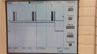
    In FIFO mode no issues but when i switch to synchronous serial mode, the issue start. I measured with my scope some signals when in serial mode that I can't explain.

    Probe 1 (top) signal from GPIO0 (data received from the transmitter)

    Probe 2 (bottom) signal at the LED (toggle after each message - before CRC check)

    scope

    When everything is OK, the bottom signal toggles after each packet.

    You can see above that the signal loose 2 packets. The fact I see the packet on the RX line, does it mean that the module is in the correct mode (in this case RX)?

    If yes I might have an issue with my adress check, is it possible in serial mode to have issue with bits synchronisation ?

  • I am really sorry but I have a real hard time understanding your different setup and what/how you are testing.

    You say that you cannot download code to the MSP 430 so I assume that you are doing your testing with your own MCU connected to a CC1120.

    You can still test “our” code examples, but you need to port them to run on your MCU

    You should then test the following:

    Use SmartRF Studio + TrxEB (with CC1120) as the transmitter.

    For the receiver, start by writing a small test program that use FIFO mode, and confirm that you can receive all messages.

    Second, port the serial example that I have referred to, to run on your MCU.

    Use default settings from the example and test with Studio as a transmitter.

    I added toggling a LED to the code example, and where able to receive all packets:

    You can also test with a payload pattern that is easy to recognize. You can then manually monitor the packets to see that the radio is receiving what is transmitted.

    With the default settings in the serial example, the radio is automatically doing the sync search for you, so the clock is not output on a GPIO before sync is received.

    I transmitted the following packet from SmartRF Studio:

    Preamble:0xAAAAAA

    Sync: 0xD39151DE

    Length: 0x06

    Payload: 0xFFAACCFF3355

    CRC: 2 bytes

    As seen below, you can recognize the Length and the payload from what is transmitted.

    Siri

  • Hello,

    Thanks for your support Siri. I ll work on your examples. With the informations you gave me i cannot failed !

    I ll note this case as "resolved"

    Best Regards

    Charles