Other Parts Discussed in Thread: TEST2
Hello,
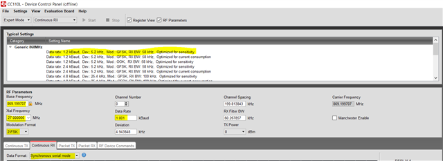
I'm trying to use the CC110L to build an 869.200 MHz receiver, previously based on a (now obsolete) ATA5761 chip. This wireless system uses a rather primitive packet format, based on 1 Kbaud Manchester encoding: 24 bits preamble, then one start bit, and then a 3-byte or 4-byte payload (also see https://e2e.ti.com/support/wireless-connectivity/sub-1-ghz-group/sub-1-ghz/f/sub-1-ghz-forum/981145/cc1101-compatibility-with-obsolete-fsk-transmitter-receiver-circuits for more details on this).
As this old system is still in use with numerous customers, I need to support the old packet format. After carefully reading the CC110L datasheet, my conclusion is that I can only use the synchronous serial mode, as there are no sync words, just one start bit. So I set up GDO0 for data output, and GDO2 as a clock output, both connected to an MCU, which takes care of decoding the received data stream.
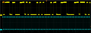
Setting up the CC110L has succeeded to a certain extent, but for the past days, I have not been able to get a coherent data stream, just noise on the data line and 8-bit bursts on the clock line:
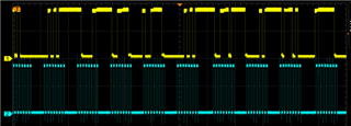
(Yellow = GDO0 = Data, Blue = GDO2 = clock)
The fact that the clock bursts are exactly the desired 1 kHz frequency suggests that setting up the Data Rate has succeeded, but obviously, things are not configured correctly. My problem is that I have no experience with building/programming receivers, so I don't know what I'm doing wrong, and what values are more or less sane for things like AGC.
Setting up synchronous serial mode is done according to the description in paragraph 5.26.2 of the datasheet, "Synchronous Serial Operation"
About the frequency and channel setup: the desired frequency is 869.2 MHz. So:
fosc = 27MHz
FREQ2:FREQ1:FREQ0 = 0x20310D =2109709 => Base frequency = 869.1733246 MHz
MDMCFG0.CHANSPC_M = 3, MDMCFG1.CHANSPC_E = 0, CHANNR.CHAN = 0 => Channel offset = 26.67618 kHz
So unless I made a mistake, Channel 1 should be located at 869.1733246 + 0.02667618 = 869.2000008 MHz
Below is the full register list and all their values. All yellow values are modified with the desired parameters; all unmarked values between square brackets are the unchanged reset values.
I left a lot of parameters unchanged, and obviously that can be part of the problem. Could someone take a look and identify possible other parameters that need to be set? Or does anyone have sample code that shows settings for a working synchronous serial mode receiver?
Then there is this: lots of fields have this comment in the datasheet: "Use setting from SmartRF Studio". The problem is that SmartRF Studio requires Windows, but I don't have Windows, only Linux, so I can't run SmartRF Studio (it doesn't work in Wine or the Mono Runtime Environment). Are these undocumented and unexplained settings important in any way?
Lastly: are there any good sources that explain in more detail how to set up a radio receiver like this? I have only very limited RF design experience (mostly transmitters, filters and shielding techniques), and I think I should learn a bit more about receiver systems.
Thanks in advance for any further advice!
|
Name |
Address |
Value |
Description |
|
GDO2_CFG |
0x00 |
0x0B |
GDO2: Serial Synchronous Clock Out |
|
GDO1_CFG |
0x01 |
[0x2E] |
[GDO1: SPI-SO] |
|
GDO0_CFG |
0x02 |
0x0C |
GDO0: Serial Synchronous Clock Out |
|
FIFOTHR |
0x03 |
[0x07] |
RX FIFO and TX FIFO thresholds |
|
SYNC1 |
0x04 |
[0xD3] |
Sync word, high byte (not used in synchronous serial mode) |
|
SYNC0 |
0x05 |
[0x91] |
Sync word, low byte (not used in synchronous serial mode) |
|
PKTLEN |
0x06 |
[0xFF] |
Packet length (not used in synchronous serial mode) |
|
PKTCTRL1 |
0x07 |
[0x40] |
Packet automation control (not used in synchronous serial mode) |
|
PKTCTRL0 |
0x08 |
0x52 |
Packet automation control -> Infinite packet length |
|
ADDR |
0x09 |
[0x00] |
Device address (not used in synchronous serial mode) |
|
CHANNR |
0x0A |
0x01 |
Channel # 1 |
|
FSCTRL1 |
0x0B |
[0x0F] |
Frequency synthesizer control |
|
FSCTRL0 |
0x0C |
[0x00] |
Frequency synthesizer control |
|
FREQ2 |
0x0D |
0x20 |
Frequency control word, high byte |
|
FREQ1 |
0x0E |
0x31 |
Frequency control word, middle byte |
|
FREQ0 |
0x0F |
0x0D |
Frequency control word, low byte -> 869.1733246 MHz |
|
MDMCFG4 |
0x10 |
0xB5 |
Modem configuration -> Channel Bandwidth = 120.5357143 kHz |
|
MDMCFG3 |
0x11 |
0x37 |
Modem configuration -> Symbol rate = 1.0010004 kHz |
|
MDMCFG2 |
0x12 |
0x08 |
Modem configuration -> 2-FSK, Manchester encoding, no preamble |
|
MDMCFG1 |
0x13 |
0x20 |
Modem configuration |
|
MDMCFG0 |
0x14 |
0x03 |
Modem configuration -> Channel spacing = 26.67617798 kHz |
|
DEVIATN |
0x15 |
[0x47] |
Modem deviation setting |
|
MCSM2 |
0x16 |
[0x07] |
Main Radio Control State Machine configuration |
|
MCSM1 |
0x17 |
0x3C |
Main Radio Control State Machine configuration -> Stay in RX mode |
|
MCSM0 |
0x18 |
[0x04] |
Main Radio Control State Machine configuration -> Manual calibration |
|
FOCCFG |
0x19 |
[0x36] |
Frequency Offset Compensation configuration |
|
BSCFG |
0x1A |
[0x6C] |
Bit Synchronization configuration |
|
AGCCTRL2 |
0x1B |
[0x03] |
AGC control |
|
AGCCTRL1 |
0x1C |
[0x40] |
AGC control |
|
AGCCTRL0 |
0x1D |
[0x91] |
AGC control |
|
Not Used |
0x1E - 0x1F |
||
|
RESERVED |
0x20 |
||
|
FREND1 |
0x21 |
[0x56] |
Front end RX configuration |
|
FREND0 |
0x22 |
[0x10] |
Front end TX configuration |
|
FSCAL3 |
0x23 |
[0xA9] |
Frequency synthesizer calibration |
|
FSCAL2 |
0x24 |
[0x0A] |
Frequency synthesizer calibration |
|
FSCAL1 |
0x25 |
[0x20] |
Frequency synthesizer calibration |
|
FSCAL0 |
0x26 |
[0x13] |
Frequency synthesizer calibration |
|
Not Used |
0x27 - 0x28 |
||
|
RESERVED |
0x29 |
[0x59] |
|
|
RESERVED |
0x2A |
[0x7F] |
|
|
RESERVED |
0x2B |
[0x3F] |
|
|
TEST2 |
0x2C |
[0x88] |
Various test settings |
|
TEST1 |
0x2D |
[0x31] |
Various test settings |
|
TEST0 |
0x2E |
[0x07] |
Various test settings |
|
SRX |
0x34 |
Command strobe: enable RX |