Hello,
i'm trying the cc110L transceiver at 434MHz. I've built two pcbs: transmitter and receiver, separately.
In both of them, the spi bus is working at 100KHz and I can write/read registers as chip version, chip status, RSSI, number of bytes in TX and RX FIFO, etcetera. The RF filter is exactly the same.
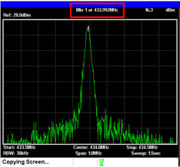
The Tx part seems ok. I attach a picture took from the SA centered at 434MHz. Sending small variable packets (< 20bytes) with address check, no broadcast, 0x21. First I flush the tx fifo during idle state, then I write the payload (plus length and address check) to the tx fifo, then calibrate and enable the synthesizer and transmitter (with strobe commands) and wait for the digital GPIO-0 to fall when the packet has been sent. GPIO-0 is configured with 0x06
The problem I have is in the receiver: the same parameters were charged from the SmartRFStudio in the initialization. Then, I do the calibration and enabling of the synthesizer and receiver (with strobe commands). Two questions:
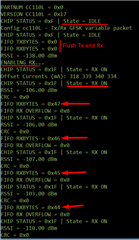
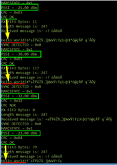
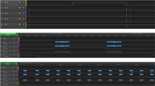
1.- In the receiver, I do a spi polling every 2 seconds, and the RX FIFO has a certain variable number of bytes that are decreasing every time I read the fifo. But the GPIO0-O is not signaling any valid packet. GPIO-0 is configured with 0x06. I attach a screen shot of what I watch on my console. Is this a expected behavior? Why is the FIFO filling with "valid packets" supposedly?
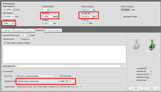
2.- When I start to send packets from my transmitter, I don't see any activity in GPIO-0 in my receiver, so maybe it's not detecting preamble or sync word as I understand. I used the recommended parameters given in Smart Rf Studio. I also attach it. So, what might it be happening? I'd like you to give me some suggestions to try, before start changing parameters in the modem or the frequency offset or data rate or RX BW or whatever ...
Thank you very much.
Jose
# Address Config = Address check, no broadcast
# Base Frequency = 433.999969
# CRC Autoflush = false
# CRC Enable = true
# Carrier Frequency = 433.999969
# Channel Spacing = 199.951172
# Data Format = Normal mode
# Data Rate = 1.19948
# Deviation = 5.157471
# Device Address = 21
# Manchester Enable = false
# Modulated = true
# Modulation Format = 2-FSK
# Packet Length = 255
# Packet Length Mode = Variable packet length mode. Packet length configured by the first byte after sync word
# Preamble Count = 4
# RX Filter BW = 58.035714
# Sync Word Qualifier Mode = 30/32 sync word bits detected
# TX Power = -15
# PA table
#define PA_TABLE {0x1d,0x00}
# ---------------------------------------------------
# Packet sniffer stttings for CC110L
# ---------------------------------------------------
IOCFG0        |0x0002|0x06|GDO0 Output Pin Configuration
FIFOTHR       |0x0003|0x47|RX FIFO and TX FIFO Thresholds
PKTCTRL1      |0x0007|0x05|Packet Automation Control
PKTCTRL0      |0x0008|0x05|Packet Automation Control
ADDR          |0x0009|0x21|Device Address
FSCTRL1       |0x000B|0x06|Frequency Synthesizer Control
FREQ2         |0x000D|0x10|Frequency Control Word, High Byte
FREQ1         |0x000E|0xB1|Frequency Control Word, Middle Byte
FREQ0         |0x000F|0x3B|Frequency Control Word, Low Byte
MDMCFG4       |0x0010|0xF5|Modem Configuration
MDMCFG3       |0x0011|0x83|Modem Configuration
MDMCFG2       |0x0012|0x03|Modem Configuration
DEVIATN       |0x0015|0x15|Modem Deviation Setting
MCSM0         |0x0018|0x18|Main Radio Control State Machine Configuration
FOCCFG        |0x0019|0x16|Frequency Offset Compensation Configuration
RESERVED_0X20 |0x0020|0xFB|Use setting from SmartRF Studio
FSCAL3        |0x0023|0xE9|Frequency Synthesizer Calibration
FSCAL2        |0x0024|0x2A|Frequency Synthesizer Calibration
FSCAL1        |0x0025|0x00|Frequency Synthesizer Calibration
FSCAL0        |0x0026|0x1F|Frequency Synthesizer Calibration
TEST2         |0x002C|0x81|Various Test Settings
TEST1         |0x002D|0x35|Various Test Settings
TEST0         |0x002E|0x09|Various Test Settings