I have a set of register values that have been taken from a previous design (that used values generated from SmartRF Studio).
I can read and write registers fine over SPI after a reset, checking CHIP_RDYn etc. However when I issue an SRX cmd to enter RX mode, every time I try and read a register, the contents always come back as 0xx00. I'll paste some debug output below, but it's not very exciting.
I wasn't actually needing to read a register at this stage but I wanted to read the MARCSTATE register just for fun to check it has gone into RX mode (or some settling state while it calibrated). At some point in the future I will want to read the RSSI when I am processing a receive packet, but that's for another day.
There was a note in section 3.1.2 of the User's Guide that implies you shouldn't really fiddle with the registers in any state other than IDLE, but it doesn't say you can't read any?
Seeing as the values are 0x00 I wouldn't trust trying to read the STATUS register because it would normally be 0x00 if in IDLE mode anyway, so I wouldn't be able to tell the difference
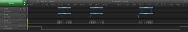
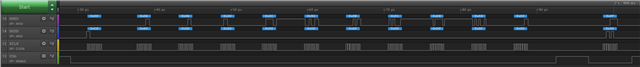
RF Transceiver (CC1200) is present.
RF Transceiver is ready.
AGC_CFG0_REG_ADDR = 0x87
AGC_CFG1_REG_ADDR = 0x51
AGC_CS_THR_REG_ADDR = 0xec
CHAN_BW_REG_ADDR = 0x0b
FIFO_CFG_REG_ADDR = 0x00
FS_CAL0_REG_ADDR = 0x0e
FS_CAL1_REG_ADDR = 0x40
FS_CFG_REG_ADDR = 0x14
FS_DIG0_REG_ADDR = 0xaf
FS_DIG1_REG_ADDR = 0x07
FS_DIVTWO_REG_ADDR = 0x03
FS_DSM0_REG_ADDR = 0x33
FS_DVC0_REG_ADDR = 0x17
FS_PFD_REG_ADDR = 0x00
FS_REG_DIV_CML_REG_ADDR = 0x1c
FS_SPARE_REG_ADDR = 0xac
FS_VCO0_REG_ADDR = 0xb5
IF_ADC0_REG_ADDR = 0x10
IF_ADC1_REG_ADDR = 0xee
IQIC_REG_ADDR = 0xcb
MDMCFG2_REG_ADDR = 0x08
MODCFG_DEV_E_REG_ADDR = 0x03
PA_CFG1_REG_ADDR = 0x6d
PKT_CFG0_REG_ADDR = 0x20
PKT_CFG1_REG_ADDR = 0x00
PKT_CFG2_REG_ADDR = 0x03
PKT_LEN_REG_ADDR = 0xff
PREAMBLE_CFG0_REG_ADDR = 0x8a
PREAMBLE_CFG1_REG_ADDR = 0x00
SERIAL_STATUS_REG_ADDR = 0x08
SYMBOL_RATE0_REG_ADDR = 0x4e
SYMBOL_RATE1_REG_ADDR = 0x62
SYMBOL_RATE2_REG_ADDR = 0x70
XOSC1_REG_ADDR = 0x03
XOSC5_REG_ADDR = 0x0e
write to IOCFG3_REG_ADDR returned 0.
IOCFG3_REG_ADDR = 0x11
write to IOCFG2_REG_ADDR returned 0.
IOCFG2_REG_ADDR = 0x09
Entering RX mode...
MARCSTATE_REG_ADDR = 0x00
IOCFG3_REG_ADDR = 0x00, status = 0
IOCFG2_REG_ADDR = 0x00, status = 0
IOCFG1_REG_ADDR = 0x00, status = 0
FREQ0_REG_ADDR = 0x00
FREQ1_REG_ADDR = 0x00
FREQ2_REG_ADDR = 0x00
SYNC_CFG1_REG_ADDR = 0x00
DEVIATION_M_REG_ADDR = 0x00
DCFILT_CFG_REG_ADDR = 0x00
MDMCFG1_REG_ADDR = 0x00
MDMCFG0_REG_ADDR = 0x00
AGC_REF_REG_ADDR = 0x00
AGC_CFG3_REG_ADDR = 0x00
FREQOFF_CFG_REG_ADDR = 0x00
MARCSTATE_REG_ADDR = 0x00