Other Parts Discussed in Thread: TEST2
Hi,
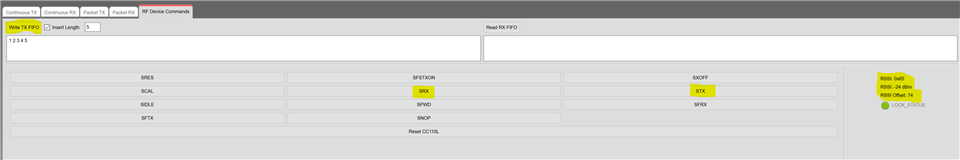
CCA Not working!!!
We have CCA issue in CC1101. We have two transmitter and two receiver on same frequency(Same Channel) but different address. Both are working individually perfectly but at same time transmitting none of them are working perfectly and it's malfunctioning. We have set CCA and CS as per below. I have done STX before TX.
TX
0x09, // IOCFG2 GDO2 Output Pin Configuration
0x2E, // IOCFG1 GDO1 Output Pin Configuration
0x80, // IOCFG0 GDO0 Output Pin Configuration
0x07, // FIFOTHR RX FIFO and TX FIFO Thresholds
0x57, // SYNC1 Sync Word, High Byte
0x43, // SYNC0 Sync Word, Low Byte
0x3E, // PKTLEN Packet Length
0x0E, // PKTCTRL1 Packet Automation Control
0x45, // PKTCTRL0 Packet Automation Control
0xFF, // ADDR Device Address
0x00, // CHANNR Channel Number
0x06, // FSCTRL1 Frequency Synthesizer Control
0x00, // FSCTRL0 Frequency Synthesizer Control
0x21, // FREQ2 Frequency Control Word, High Byte
0x65, // FREQ1 Frequency Control Word, Middle Byte
0x6A, // FREQ0 Frequency Control Word, Low Byte
0xF8, // MDMCFG4 Modem Configuration 0xCA 0xC8-100Khz
0x93, // MDMCFG3 Modem Configuration 0x83 10Kb-0x93
0x13, // MDMCFG2 Modem Configuration
0xA3, // MDMCFG1 Modem Configuration 0xA0
0xff, // MDMCFG0 Modem Configuration 0xF8
0x34, // DEVIATN Modem Deviation Setting
0x07, // MCSM2 Main Radio Control State Machine Configuration
0x2F,//0x2C, // MCSM1 Main Radio Control State Machine Configuration
0x18, // MCSM0 Main Radio Control State Machine Configuration
0x16, // FOCCFG Frequency Offset Compensation Configuration
0x6C, // BSCFG Bit Synchronization Configuration
0x43, // AGCCTRL2 AGC Control
0x50, // AGCCTRL1 AGC Control
0x91, // AGCCTRL0 AGC Control
0x02, // WOREVT1 High Byte Event0 Timeout
0x26, // WOREVT0 Low Byte Event0 Timeout
0x09, // WORCTRL Wake On Radio Control
0x56, // FREND1 Front End RX Configuration
0x17, // FREND0 Front End TX Configuration
0xA9, // FSCAL3 Frequency Synthesizer Calibration
0x0A, // FSCAL2 Frequency Synthesizer Calibration
0x00, // FSCAL1 Frequency Synthesizer Calibration
0x11, // FSCAL0 Frequency Synthesizer Calibration
0x41, // RCCTRL1 RC Oscillator Configuration
0x00, // RCCTRL0 RC Oscillator Configuration
0x59, // FSTEST Frequency Synthesizer Calibration Control,
0x7F, // PTEST Production Test
0x3F, // AGCTEST AGC Test
0x81, // TEST2 Various Test Settings
0x3F, // TEST1 Various Test Settings
0x0B // TEST0 Various Test Settings
RX
0x0E,//0x09, // IOCFG2 GDO2 Output Pin Configuration
0x2E, // IOCFG1 GDO1 Output Pin Configuration
0x80, // IOCFG0 GDO0 Output Pin Configuration
0x07, // FIFOTHR RX FIFO and TX FIFO Thresholds
0x57, // SYNC1 Sync Word, High Byte
0x43, // SYNC0 Sync Word, Low Byte
0x3E, // PKTLEN Packet Length
0x0E, // PKTCTRL1 Packet Automation Control
0x45, // PKTCTRL0 Packet Automation Control
0xFF, // ADDR Device Address
0x00, // CHANNR Channel Number
0x06, // FSCTRL1 Frequency Synthesizer Control
0x00, // FSCTRL0 Frequency Synthesizer Control
0x21, // FREQ2 Frequency Control Word, High Byte
0x65, // FREQ1 Frequency Control Word, Middle Byte
0x6A, // FREQ0 Frequency Control Word, Low Byte
0xF8, // MDMCFG4 Modem Configuration 0xCA 0xC8-100Khz
0x93, // MDMCFG3 Modem Configuration 0x83 10Kb-0x93
0x17,//0x13, // MDMCFG2 Modem Configuration
0xA3, // MDMCFG1 Modem Configuration 0xA0
0xff, // MDMCFG0 Modem Configuration 0xF8
0x34, // DEVIATN Modem Deviation Setting
0x07, // MCSM2 Main Radio Control State Machine Configuration
0x2C, // MCSM1 Main Radio Control State Machine Configuration
0x18, // MCSM0 Main Radio Control State Machine Configuration
0x16, // FOCCFG Frequency Offset Compensation Configuration
0x6C, // BSCFG Bit Synchronization Configuration
0x43, // AGCCTRL2 AGC Control
0x50, // AGCCTRL1 AGC Control
0x91, // AGCCTRL0 AGC Control
0x02, // WOREVT1 High Byte Event0 Timeout
0x26, // WOREVT0 Low Byte Event0 Timeout
0x09, // WORCTRL Wake On Radio Control
0x56, // FREND1 Front End RX Configuration
0x17, // FREND0 Front End TX Configuration
0xA9, // FSCAL3 Frequency Synthesizer Calibration
0x0A, // FSCAL2 Frequency Synthesizer Calibration
0x00, // FSCAL1 Frequency Synthesizer Calibration
0x11, // FSCAL0 Frequency Synthesizer Calibration
0x41, // RCCTRL1 RC Oscillator Configuration
0x00, // RCCTRL0 RC Oscillator Configuration
0x59, // FSTEST Frequency Synthesizer Calibration Control,
0x7F, // PTEST Production Test
0x3F, // AGCTEST AGC Test
0x81, // TEST2 Various Test Settings
0x3F, // TEST1 Various Test Settings
0x0B // TEST0 Various Test Settings