This thread has been locked.

If you have a related question, please click the "Ask a related question" button in the top right corner. The newly created question will be automatically linked to this question.

CC115L: FIFO underflow and CHIP_RDYn = 1 on STX command.

Part Number: CC115L
Other Parts Discussed in Thread: MSP430FW423, MSP430FW425,

Hello,

1. We are producing working devices using MSP430FW423/MSP430FW425 and cc115l as radio transmitter.

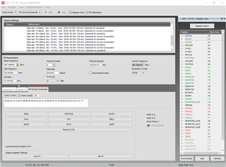
2. We are using configuration form RFStudio with default values for "100kb optimized for current consumption". Configuration process is shown on attachment1 and source for saleae logic2 is here: https://www.dropbox.com/s/whc609zdau98lty/34.C.05%20cc%20configuration%20attachement1.sal?dl=0

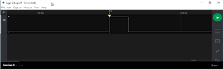
3. We are sending data and reacting on GDO pin that is setup for 0x06 (Asserts when sync word has been sent, and de-asserts at the end of the packet. The pin will de-assert if the TX FIFO underflows.) This is shown in attachement2 (https://www.dropbox.com/s/8cfund2a2snh4j3/34.C.05%20cc%20normal%20send%20attachement2.sal?dl=0)

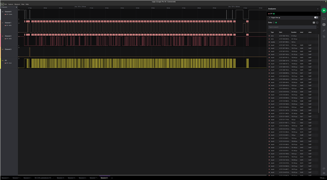
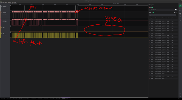
4. Now for our latest production we have problem with fifo underflow error randomly showing when trying to send frame. See attachement 3 (https://www.dropbox.com/s/784a0py70dfkn2u/34.C.05%20cc%20send%20with%20underflow%20attachement3.sal?dl=0)

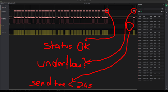
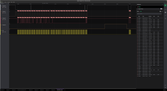
5. right after that frame we try to send next one. We perform fifo flush, which succeded and send data to fifo (status is 0x0F -> OK!!) and when performing STX command we get 0xFE status that indicates clock or voltage error. GDO is not asserted and module stays in TX mode. Carier is enabled and module consumes 35 mA of constant current. see attachement 4 (https://www.dropbox.com/s/vicgmbfnu87butl/34.C.05%20cc%20send%20CHIP_RDYn%201%20attachement4.sal?dl=0)

6. After that we have timeout in master uC and cc115l is reset and reprogrammed again. After reset it works as expected for couple of sends and randomly this problem returns. Sometimes after one minute, sometimes after hour. We Have about 8 errors during 4 hour period on current DUT. We haven't observed this issue on every device for now. 

What could cause the problem?

Have you seen something similar on other projects?

What other data we could provide?

What we should test to know cause of this error?

I don't see relation to errata notes here but maye I'm missing something?

Regards

 Maciej Łaski

  • Unfortunately I am not able to open the links you sent me, so I am not able to get a proper view of the figures you are showing.

    It would be helpful if you could provide your register export from SmartRF STudio, together with your TX code (including what packets you are trying to send). Normally TX FIFO Underflow only happen in the cases where you start TX before you have written the complete packet to the FIFO (for example if you are sending packets that are longer than the FIFO size).

    CHIP_RDYn not being low when CSn is pulled low, indicates that you have a HW problem.

    BR

    Siri

  • Hi Siri,

    You have problems with links or you can't install free saleae Logic2 software to view files?

    here are files for direct download:

    www.dropbox.com/.../34.C.05 cc configuration attachement1.sal

    www.dropbox.com/.../34.C.05 cc normal send attachement2.sal

    www.dropbox.com/.../34.C.05 cc send with underflow attachement3.sal

    www.dropbox.com/.../34.C.05 cc send CHIP_RDYn 1 attachement4.sal

    Here you have registers definition from RFstudio. It's default configuration for 100kb optimized for current consumption. Only GPIO2 changed to 0x06.

    # Register settings for CC115L
    #     - generated by SmartRF Studio 
    
    sub writeRegisters
    {
        my $dev= shift;
        $dev->writeRegister("IOCFG2",0x06);
        $dev->writeRegister("IOCFG0",0x29);
        $dev->writeRegister("PKTCTRL0",0x05);
        $dev->writeRegister("FREQ2",0x21);
        $dev->writeRegister("FREQ1",0x62);
        $dev->writeRegister("FREQ0",0x76);
        $dev->writeRegister("MDMCFG4",0x5B);
        $dev->writeRegister("MDMCFG3",0xF8);
        $dev->writeRegister("MDMCFG2",0x93);
        $dev->writeRegister("MCSM0",0x18);
        $dev->writeRegister("RESERVED_0X20",0xFB);
        $dev->writeRegister("FSCAL3",0xEA);
        $dev->writeRegister("FSCAL2",0x2A);
        $dev->writeRegister("FSCAL1",0x00);
        $dev->writeRegister("FSCAL0",0x1F);
        $dev->writeRegister("TEST0",0x09);
    }

    Number of bytes in fifo is correct. I've checked this. It is visible on provided datagrams. (i'm unable to share code for obvious reasons)

    "CHIP_RDYn not being low when CSn is pulled low, indicates that you have a HW problem."

    1. Hmm... right now we have soldered cc115l from our DUT to another board and problem remains. Only cc115l chip was replaced. Currently we are soldering brand new cc115l to board DUT board. (cross replace). I will keep you informed.

    2. A you can see on datagrams we are filling fifo before executing command STX. During fifo fill status is 0x0f (so everything is correct). than when fifo is filled SC is going high and then low for STX command. HERE status is 0xFE. So CHIP_RDYn = 1. Supply voltage is 3.6V and we have checked on osciloscope that it is good (without any disturbances)

    3. This product is on market for 5 years and we haven't noticed such behaviour before.

    Regards

     Maciek

  • 4. We have soldered brand new cc115l in place of that one that was soldered out from DUT. Currently we have transmitted over 700 frames on 3 hour period. No error was observed! 

    ---EDIT---

    5. After night module transmitted over 8000 frames and no error ocured.

    So, after cross replacement of cc115l in two modules the erroneus behavior is following cc115l chip.

  • Do you have many devices that are failing, and are there a chance that this could be an ESD issue?

    Siri

  • 14 "broken" devices in 4000 have been found... Might be more. 

    Those modules came back from our client on warranty and they were found during second manufacturing step (solder battery and insert into case). Our client HAVE ESD protection and is very careful about that because we had previous problems with ESD that have been confirmed. Ofcorse it can be ESD issue, but our previous problems with ESD resulted in VERY HIGH current taken by cc15l (over 500mA) (small spark from finger to antenna was enough to create such problem). Here this problem doesn't follow with high current observation.

    In our company we are producing tesging and programming those modules in PCB frames that holds 16 pices. During test and programming process we test current when module is: (unprogrammed, programmed, sleeping, sending.... and so on). We have soldered this cc115l from our DUT (that broken one) to fresh 16 pieces frame. our testing and programming haven't shown any disturbances on this module in comparision to other 15.

    If this is ESD issue, how can we check it?

    Will it be visible on Rentgen?

    Do you have any procedures to test such modules? 

    Maybe we can send some samples to your laboratory for further tests?

    It would be superb if we can say: 100% it's ESD! ... but I'm not sure.

    Maciek

  • First: Could you measure the impedance from every pin on the CC115L to ground on a "broken" device and a "working" device and post the result? (You can do this on PCB level). Normally you will see a ESD damage on lower impedance.

    You write that this product has been on the market for 5+ years. Since you have started to see issues now, have you done any changes to the production line lately? I find it strange that you suddenly start to get a fall out in an mature production setup. Is the production and test setup properly grounded?  Any BOM changes? 

  • Hello TER,

    Impedance measurements are perfectly equal on both (working and not working) boards. I was really hoping that problem will be findable by impedance check.

    I've changed firmware in portion of modules. This firmware had error. The timeout bit wasn't correctly handled so if module don’t assert GDO pin there is no sleep command and module stays in TX mode. That is how we found those units. They completely destroyed communication with other modules by having constant TX on. I've fixed this error and now timeout is correctly handled. I also send bit in main frame, that timeout have been noticed. As I said before on module which previously had bad behavior (constant tx) this bit always shows. Sometimes immiedetly, somtimes after couple of hours. On other modules this bit is not observed. Like I said before erroneous behavior is following the cc115l chip (we have soldered it to different PCB).

    THE MAIN PROBLEM is that this is not detectable on production process. Current is correct, module is sending data... Even this impedance measurement doesn't shown any disturbances. It's not many. Currently we have 14 devices on over 4000 pieces of production. It's not problem if we can detect that in production process... but it's big problem when device is send to end client.

    Is the production and test setup properly grounded?  Any BOM changes? 

    Yes and Yes. We had previous problems with ESD. Single spark on antenna and module started to consume over 500mA. We have detected that issue because battery was getting warm. After that we have ESD protection. 

    Basically, I don't see any problems with SPI and data transmission that I've send samples above. I don't know if this is problem caused by us (ESD) or it's problem with specific unit of cc115l. The cc115l with errors are from different productions with different LOT.

    Regards Maciek

  • Could you try a full A - B- A swap? Basically: 

    - Have you tried to move the failing CC115L over on a known good PCB?

    - Have you tried to replace the failing chip on a failed PCB with a known good chip? 

  • 4. We have soldered brand new cc115l in place of that one that was soldered out from DUT. Currently we have transmitted over 700 frames on 3 hour period. No error was observed! 

    ---EDIT---

    5. After night module transmitted over 8000 frames and no error ocured.

    So, after cross replacement of cc115l in two modules the erroneus behavior is following cc115l chip.

  • Would you be able to send a few failing samples to me (If that is the case, send me a friend request and I can send the address you need to ship to). I would like to take a look at this before starting a formal FA request.  

  • Do you want bare chips or we should solder them on PCB? What kind of PCB should it be? Maybe evaluation board that can be connected to RFStudio. I would like to test all cc115l that I'm going to send you and provide solution to reproduce.

  • Only chips are fine. I will find an EM on my end to solder them on to. I have accepted the friend request. 

  • I have received the HW. 

    I would like to use SmartRF Studio, a EM with the received chip on and a TRXEB. SmartRF Studio are able to send command strobes. What would be a way to reproduce what you are seeing using the above? 

  • Hi TER,

    First of all, I've send complete board (our DUT) after power on (3.6V) device should start sending and on each error you will have pin hi/low on soldered wire.

    As for your question, whole configuration and TX commands are attached in Logic diagrams above.

    1. I have used default RFStudio configuration for 100kb optimized for current. Only behaviour of GDO2 is changed to 0x06

    2. Next chip is send to sleep using SPWD (0x39) command

    3. Than I wakeup CC and fill fifo with data and send TX command multiple times in 1second period.

    4. After couple of transmissions problem occurs.

    Is it enough for you?

    Regards

    Maciek

  • I believe that should be sufficient. I plan to look into this tomorrow. 

  • I soldered one of the retured devices onto a CC115L EM and use this in combination witha TRXEB and SmartRF Studio to test:

    Testing method:

    - Select 100 kbps setting

    - Press the "Pkt TX" init 

    - Set the IOCFG to 0x06

    - Type in a random FIFO content, press "Write TX FIFO"

    - Press STX

    - Press "Write TX FIFO"

    - Press STX ....

    I monitor the GDO, see the last plot. I don't manage to trig anything with this test metode

  • Hi TER,

    Thank you for all tests.

    As a programmer I often use and hear "Here it works" sentence:).

    For those two modules sometimes we had to wait for more than 1.5 hour and we send frame every 10 seconds. So it gives 540 frames before first error. The most erroneus chip is the one in DUT thet I've sent you. On this one error ususlly happen after couple of frames after poweron. But somtimes wait time is measured in tens of minutes.

    Also I see some differences in tests:

    1. Power supply: probably you have 3.3V from test board and we have 3.65V from battery. 

    2. I don't know how rfstudio handles communication with chip? Maybe it reacts on errors and doing some additional steps to send frame...? Unfortunately I can't analize SPI communication from plot you have sent. :)

    3. Which evaluation board do you use for tests?

    Regards

     Maciek

  • 1): I assume that you got a small IR drop on your board causing the voltage on the CC115L to be 3.60 V or below? I doubt that the difference in supply will cause any differences since all the modules internally in the chip has separate LDOs.

    2) When using Studio: When selecting "RF Device Commands" only the command selected should be sent over the SPI. Meaning that is you press STX only the STX strobe is sent. 

    3) A CC115L EM. I tried to find a reference to them online but it looks like they have been removed at one point. It's very similar to https://www.ti.com/tool/CC1101EM868-915_REFDES, just with slight modifications for lower cost. Then this is attached to a TRXEB (https://www.ti.com/tool/SMARTRFTRXEBK). The reason I want to use this setup is to verify that the MCU (on your board) is not part of the problem for some reason. 

    I come in a bit late in the thread and I missed the fact that this issue can take multiple packet transmits to trig. What I have a problem to understand at the moment is: Both from a HW and a SW view, what is the difference between Tx strobe 1 and TX strobe number x (That cause an issue). The digital control used in TX for CC115L is a state machine. If this is caused by a HW issue, I would assume that the issue is trigged at a given sequence (meaning it should be reproducible). The same with SW. Have you been able to see a pattern? I guess it's easier to see on the devices that you see this often on. 

  • 1. OK

    2. OK

    3. Unfortunately I don't have any tool that I could connct to rfstudio in online mode. So I'm unable to test any reproducable patterns. I've sent all SPI commands in my first post in Saelae Logic2 format. It can be observed that every time communication from MCU look same. Second thing is that this problem occurs always on some chips and on rest it doesn't. I would be glad to help you generate problem on your board. Currently I'm trying to find such steps. 

    The best option would be checking the DUT I've send you. It has all SPI signals and on every error occurance triggers pin strobe. In that case SPI could be analyzed. Yes in that case our MCU is in tests... but SPI looks good.

    I'm trying to figure out some reproduceable tests for rfstudio...

  • Have you been able to find alternative ways to reproduce the issue? 

  • Hi TER,

    Sorry for delay but I've been banned fro ti.com, (Written simple script to refresh page and check for parts avaliability in shop... too much I assume).

    No I haven't found. I don't have development boards. Those chips I've sent have caused problems 100%. The best solution would be to attach SPI to DUT I've sent you and power in on. You should be able to catch erroneous behaviour in couple of minutes max.

    Regards Maciek

  • I assume checking the SPI lines with a logic analyzer will get the same plots as you posted originally. Have you checked the lines with an oscilloscope to check if the logic analyzer gives a correct picture (if the logic levels or the rise/ fall times are off what you see on the analyzer may not be correct compared to how the chip handles the levels. It could be that your design is marginal and that things work for some chips but not others dependent on the VOL/ VOH levels. 

    Looking at the plots again it's not clear if you are following:

    "When CSn is pulled low, the MCU must wait until CC115L SO pin goes low before starting to transfer the header byte. This indicates that the crystal is running. Unless the chip was in the SLEEP or XOFF states, the SO pin will always go low immediately after taking CSn low."

    from the datasheet. The values you read out, even early in a transaction, does not look as expected at times.


  • Siri wrote a code to mimic the plots you have posted. The HW used in a CC115L EM (with one of the returned samples) on a TRXEB:

    The code is running in an infinite loop:

    while(TRUE) {
          
        writeTest(); // Write to the test registers
          
        createPacket(txBuffer);
    
        // Write packet to TX FIFO with SFTX first
        cc11xLSpiWriteTxFifoWithFlush(txBuffer,sizeof(txBuffer));
    
        // Strobe TX to send packet
        trxSpiCmdStrobe(CC115L_STX);
         
        while(packetSemaphore != ISR_ACTION_REQUIRED);
    
        // Clear semaphore flag
        packetSemaphore = ISR_IDLE;
    
        packetCounter++;
    
        // Enter SLEEP    
        status = trxSpiCmdStrobe(CC115L_SPWD);
         
        // If status is for example TX FIFO Underflow (0x7F), LCD will show ERROR and the code will     
        // hang
        if (status != 0x0F)
        {
            lcdBufferClear(0);
            lcdBufferPrintString(0, "ERROR", 0, eLcdPage0);
            lcdSendBuffer(0);
            while(1);
        }
        else
        {
            // Update LCD with packet counter
            updateLcd();
        }
    }
    

    Note that the SPI function always polls on CHIP_RDYn, if this is not set the code will hang. 

    If an error occur, the code will hang. This code has been running over night, so far over 7M packets has been sent so this has not been able to trig an error on our side. 

  • Hi TER,

    "I assume checking the SPI lines with a logic analyzer will get the same plots as you posted originally. Have you checked the lines with an oscilloscope to check if the logic analyzer gives a correct picture (if the logic levels or the rise/ fall times are off what you see on the analyzer may not be correct compared to how the chip handles the levels. It could be that your design is marginal and that things work for some chips but not others dependent on the VOL/ VOH levels."

    Yes and yes. Scope is showing correct signal levels.

    "When CSn is pulled low, the MCU must wait until CC115L SO pin goes low before starting to transfer the header byte. This indicates that the crystal is running. Unless the chip was in the SLEEP or XOFF states, the SO pin will always go low immediately after taking CSn low."

    True. In first attachement you can see chip configuration.

    In second attachement there is "normal frame send". You can see that right after CS low we have SO hi drived by cc115l. I have small delay between CS low to SO hi. Than I wait until SO goes low.

    Than there is third attachement that shows erroneous behaviour during TX command strobe. You can see that cc115l correctly drive SO hi after CS low and there is correct wait until CS falls down.

    Last attachement, there is a problem you have mentioned. BUT!!! cc115l doesn't drive SO pin hi after my CS low so my wait for SO low procedure finishes immiedetly (SO is actualy low). And yes 0x7F is received from first response byte. But this happens after first error during TX strobe in previous frame.

    I've checked and I think, I have every timing and wait loop correct. Maybe here is my problem that I'm unable to see.

  • Hello TER, Hello Siri,

    OK, what i don't understand is:

    1. failure cc115l have been replaced with new one and problem dissapeared.

    2. failure cc115l have been soldered to different working PCB and problem followed erroneous chip.

    3. Same erroneous chip works correctly in your design (test board) :/ Maybe something is different on PCB's my and yours...?

    So currently I need help to find why and where are errors in my design. The PCB and code I've send you (DUT).

    Can you provide SPI plots from your test code?

    Regards Maciek.

  • Please find the SPI plots above. 

    Do you have an overview of which nodes I can monitor on the test pads on the PCB you sent me? 

  • Hello,

    Thank you for plots. I'm analyzing them.

    I've send you paper with pinout description. Unfortunately I can't find it here. Probably I just wrote description, print and forget.

    As I remember there is a wire soldered to one of test pads that are on bottom of PCB. This one should indicate error. (HI->LO strobe). SPI is easy to check on CC115L pinout. SPI pins are also soldered and can be observed using logic analyzer. They are connected to PINS: P1.2(51), P1.3(50), P1.4(49), P1.7(46), P5.5(41) of MSP430.

  • I don't have the PCB in front of me. If I remember correctly I noticed a fair number of test points on the PCB and wondered about which signals that are available on these. 

  • Most of them are for programming purposes. That's why I've soldered wires and goldpins for easier analyzer / scope plugin.

  • Hello Torstein and Siri,

    Thank you for your continued support. As the customer's FAE, I just want to ask what can be done to help speed up the process of finding the root cause of these errors? 

    As I understand, it is not yet clear if the issue lies with the CC115L chips in question or the specific PCB design, as some of the "broken" parts worked on the EVM. 14 "broken" parts out of 4000 across multiple lots seems to indicate some issues on the board, perhaps some borderline stable conditions.

    I assume that it is the case, but can we also check if these lots were from different silicon wafers? 
    Maciek, could you please send me the lot numbers and your order numbers?

    I think the below summary from Maciek summarizes where we currently stand:

    1. failure cc115l have been replaced with new one and problem disappeared.

    2. failure cc115l have been soldered to different working PCB and problem followed erroneous chip.

    3. Same erroneous chip works correctly in your design (test board) :/ Maybe something is different on PCB's my and yours...?

    TER, were you able to test the chips on the customer's board? From what I understand, you were only able to test on the EVM. I think that progress in finding the root cause of these issues will be difficult without rigorous testing on the original PCB and following the same test procedure.

    Thank you and I would be happy to move this to email communication if it helps.

    Daniel Waleniak

  • When we receive chips where a customer has seen errors in the production line we always use EMs for testing. The objective for our testing to to verify that the error observed is from the chip it self. We therefore want to do this testing with known good HW (PCB) and SW. We have not seen any failures when testing one of the returned units using this method. 

    Testing on a customer board for this type of issue has limited upside since both the HW and SW is unknown (seen from our side). If I measure on the board I have received I expect that I see the failure (if not, I would not have received the board in the first place). But the board is a black box, I'm able to monitor a few signals, but not able to change anything. 

    Is it possible for the customer to run the exact same (highlevel) SW on the board as we have used?  

  • Hi,

    Is it possible for the customer to run the exact same (highlevel) SW on the board as we have used?  

    Yes, but it has some limitations. MCU we use doesn't have hardware SPI so we simulate it using gpio.

  • These are LOT's for CC115L that caused problems:

    0212095T40
    1069674T41
    1191567T41
    1319651T41

  • It's possible to write a SW SPI that has the required timing. And hence it should be possible to port the short example we used to your HW , run it and compare the traffic on the SPI bus to see if you are doing the same as we did on a EM.  

  • Yes. That's obvious. 

    I have written SPI simulation and I'm sure that required timings are satisfied. The problem is I can be wrong. Can you point place on where timings are incorrect on plots that I've send in first post?

    Can you provide code that you want me to run for tests? So it won't be my code.

  • I'm thinking about the code I posted 19 days ago and the SPI plots I posted 14 days ago. This was what I used to test one of the returned samples with and that didn't trigger an error. 

  • I'm looking at the PCB: For the SPI interface, is it some test points where I can solder on wires? Any pointers, drawings how I should solder on wires? 

  • Hi TER,

    I was wondering if you have any feedback to share since last week?

    Thanks,

    Daniel

  • I'm not in the lab today but I have looked at the original Salee plots again to see if something else than timing could cause an issue. 

    I see from the plot "cc send with underflow attachement3.sal" that the packet length is different than the first attachment which is a TX that goes without errors. Is it any correlation between packet length and the underflow error?  (in case of a strange stuck at error etc) Also in the case with an underflow error, have you checked what the device actually send in this case?