Hi Team,
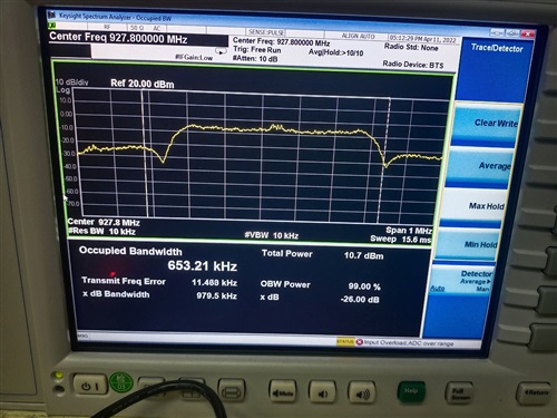
My customer is using CC1312 and they can not pass JAPAN occupied band-width test.
They try to lower TX Power but the OBW test still fail.
Please help to provide comments. Thanks.

This thread has been locked.
If you have a related question, please click the "Ask a related question" button in the top right corner. The newly created question will be automatically linked to this question.
Hi,
Please can you provide more information about the measurement performed:
Regards,
Zack
Hi,
Please check the following:
//*********************************************************************************
// Generated by SmartRF Studio version 2.23.0 (build#300)
// The applied template is compatible with cc13x2_26x2 SDK version 2.10.xx.xx or newer.
// Device: CC1312R Rev. E (2.1).
//
//*********************************************************************************


//*********************************************************************************
// Parameter summary
// Frequency: 927.80000 MHz
// Data Format: Serial mode disable
// Deviation: 190.000 kHz
// IEEE 802.15.4g Packet Length: 20
// Select bit order to transmit PSDU octets: 1
// Packet Data: 255
// Preamble Count: 7 Bytes
// Preamble Mode: Send 0 as the first preamble bit
// RX Filter BW: 1092.5 kHz
// Symbol Rate: 500.00000 kBaud
// Sync Word: 0x0055904e
// Sync Word Length: 24 Bits
// TX Power: 7 dBm
// Whitening: Dynamically IEEE 802.15.4g compatible whitener and 16/32-bit CRC

#include "smartrf_settings.h"

#include DeviceFamily_constructPath(rf_patches/rf_patch_cpe_prop.h)

// TI-RTOS RF Mode Object
RF_Mode RF_prop =
{
    .rfMode = RF_MODE_AUTO,
    .cpePatchFxn = &rf_patch_cpe_prop,
    .mcePatchFxn = 0,
    .rfePatchFxn = 0
};


// Overrides for CMD_PROP_RADIO_DIV_SETUP
uint32_t pOverrides[] =
{
    // override_prop_common.xml
    // DC/DC regulator: In Tx, use DCDCCTL5[3:0]=0x7 (DITHER_EN=0 and IPEAK=7).
    (uint32_t)0x00F788D3,
    // override_prop_common_sub1g.xml
    // Set RF_FSCA.ANADIV.DIV_SEL_BIAS = 1. Bits [0:16, 24, 30] are don't care..
    (uint32_t)0x4001405D,
    // Set RF_FSCA.ANADIV.DIV_SEL_BIAS = 1. Bits [0:16, 24, 30] are don't care..
    (uint32_t)0x08141131,
    // override_tc178.xml
    // Synth: Set loop bandwidth after lock to 40 kHz (K2)
    (uint32_t)0x29200583,
    // Synth: Set loop bandwidth after lock to 40 kHz (K2)
    (uint32_t)0x000005A3,
    // Synth: Set loop bandwidth after lock to 40 kHz (K3, LSB)
    (uint32_t)0xF5700603,
    // Synth: Set loop bandwidth after lock to 40 kHz (K3, MSB)
    (uint32_t)0x00000623,
    // Synth: Set FREF = 4 MHz
    (uint32_t)0x000C84A3,
    // Tx: Configure PA ramp time, PACTL2.RC=0x1 (in ADI0, set PACTL2[4:3]=0x1)
    ADI_2HALFREG_OVERRIDE(0,16,0x8,0x8,17,0x1,0x0),
    // Rx: Set AGC reference level to 0x30 (default: 0x2E)
    HW_REG_OVERRIDE(0x609C,0x0030),
    // Rx: Set RSSI offset to adjust reported RSSI by -4 dB (default: -2), trimmed for external bias and differential configuration
    (uint32_t)0x000488A3,
    // Rx: Set anti-aliasing filter bandwidth to 0xA (in ADI0, set IFAMPCTL3[7:4]=0xA)
    ADI_HALFREG_OVERRIDE(0,61,0xF,0xA),
    // Tx: Set wait time before turning off ramp to 0x1A (default: 0x1F)
    HW_REG_OVERRIDE(0x6028,0x001A),
    // Set LNA IB offset to 0xF
    (uint32_t)0x000F8883,
    (uint32_t)0xFFFFFFFF
};


// CMD_PROP_RADIO_DIV_SETUP
// Proprietary Mode Radio Setup Command for All Frequency Bands
rfc_CMD_PROP_RADIO_DIV_SETUP_t RF_cmdPropRadioDivSetup =
{
    .commandNo = 0x3807,
    .status = 0x0000,
    .pNextOp = 0, // INSERT APPLICABLE POINTER: (uint8_t*)&xxx
    .startTime = 0x00000000,
    .startTrigger.triggerType = 0x0,
    .startTrigger.bEnaCmd = 0x0,
    .startTrigger.triggerNo = 0x0,
    .startTrigger.pastTrig = 0x0,
    .condition.rule = 0x1,
    .condition.nSkip = 0x0,
    .modulation.modType = 0x1,
    .modulation.deviation = 0x2F8,
    .modulation.deviationStepSz = 0x0,
    .symbolRate.preScale = 0xF,
    .symbolRate.rateWord = 0x50000,
    .symbolRate.decimMode = 0x0,
    .rxBw = 0x60,
    .preamConf.nPreamBytes = 0x7,
    .preamConf.preamMode = 0x0,
    .formatConf.nSwBits = 0x18,
    .formatConf.bBitReversal = 0x0,
    .formatConf.bMsbFirst = 0x1,
    .formatConf.fecMode = 0x0,
    .formatConf.whitenMode = 0x7,
    .config.frontEndMode = 0x0,
    .config.biasMode = 0x1,
    .config.analogCfgMode = 0x0,
    .config.bNoFsPowerUp = 0x0,
    .config.bSynthNarrowBand = 0x0,
    .txPower = 0x26D4,
    .pRegOverride = pOverrides,
    .centerFreq = 0x039F,
    .intFreq = 0x0800,
    .loDivider = 0x05
};


// CMD_FS
// Frequency Synthesizer Programming Command
rfc_CMD_FS_t RF_cmdFs =
{
    .commandNo = 0x0803,
    .status = 0x0000,
    .pNextOp = 0, // INSERT APPLICABLE POINTER: (uint8_t*)&xxx
    .startTime = 0x00000000,
    .startTrigger.triggerType = 0x0,
    .startTrigger.bEnaCmd = 0x0,
    .startTrigger.triggerNo = 0x0,
    .startTrigger.pastTrig = 0x0,
    .condition.rule = 0x1,
    .condition.nSkip = 0x0,
    .frequency = 0x039F,
    .fractFreq = 0xCCCD,
    .synthConf.bTxMode = 0x0,
    .synthConf.refFreq = 0x0,
    .__dummy0 = 0x00,
    .__dummy1 = 0x00,
    .__dummy2 = 0x00,
    .__dummy3 = 0x0000
};


// CMD_TX_TEST
// Transmitter Test Command
rfc_CMD_TX_TEST_t RF_cmdTxTest =
{
    .commandNo = 0x0808,
    .status = 0x0000,
    .pNextOp = 0, // INSERT APPLICABLE POINTER: (uint8_t*)&xxx
    .startTime = 0x00000000,
    .startTrigger.triggerType = 0x0,
    .startTrigger.bEnaCmd = 0x0,
    .startTrigger.triggerNo = 0x0,
    .startTrigger.pastTrig = 0x0,
    .condition.rule = 0x1,
    .condition.nSkip = 0x0,
    .config.bUseCw = 0x1,
    .config.bFsOff = 0x1,
    .config.whitenMode = 0x2,
    .__dummy0 = 0x00,
    .txWord = 0xFFFF,
    .__dummy1 = 0x00,
    .endTrigger.triggerType = 0x1,
    .endTrigger.bEnaCmd = 0x0,
    .endTrigger.triggerNo = 0x0,
    .endTrigger.pastTrig = 0x0,
    .syncWord = 0x0055904E,
    .endTime = 0x00000000
};
Please see the paragraph which copy from SWRA457. In customer case , the limit will be 600Khz instead of 200Khz.

Thanks.