


Our product, a custom PCB based on the CC1352P will be powered by a non-removable batter. After applying the battery, we will need to program the device.
When I program the PCB (or a CC1352 development board) using external power, then remove the programming device, the current draw is not as expected. The current draw is higher than it should be and there are no small peaks (which I understand occur because the chip is charging a capacitor on a regular schedule). If I then cycle the power, the current usage is lower, and I see the small peaks that I expect.
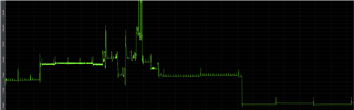
Below is a picture of the current draw during programming, then after programming is complete and the program is executing.
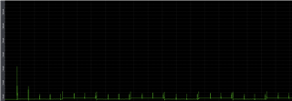
Below is a picture of the current draw after cycling the power.
I am running a simple example program that toggles an LED to try and diagnose my problem. I am using TI-RTOS.
GPIO_setConfig(CONFIG_GPIO_L, GPIO_CFG_OUT_STD | GPIO_CFG_OUT_LOW);
sleep(3);
bool on=1;
while(1) {
sleep(3);
GPIO_write(CONFIG_GPIO_L, on);
on = !on;
}
Is it possible to achieve the lower current draw seen in my second image without cycling the power? If so what changes need to be made?
Note: It's hard to completely rule out some sort of hardware issue or peripheral issue that causes the higher current draw. However, I suspect the actual CC1352 module is responsible for the increased current draw because the program does execute, but I do not see the peaks where the capacitor is charging. That would seem to indicate the CC1352 is in some sort of strange power state until power is cycled.
