This thread has been locked.

If you have a related question, please click the "Ask a related question" button in the top right corner. The newly created question will be automatically linked to this question.

LAUNCHXL-CC1352R1: TI-RTOS Clock Module Performance

Part Number: LAUNCHXL-CC1352R1
Other Parts Discussed in Thread: CC1312R, , SYSCONFIG

Hello,

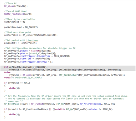
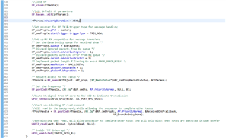
I am using the sub 1 GHz RF on the CC1352R1 to accomplish time synchronization between two CC1352R1 eval boards and to send timing signals. I am using TI-RTOS & SDK version 6.20.00.29. Once the clocks are synchronized, I calculate the next time a timing signal needs to be sent. I then use a clock object from the TI-RTOS clock module (explained here: TI-RTOS Kernel (SYS/BIOS) User's Guide, section 5.2), input the calculated time until the next time a signal needs to be sent as a timeout to the clock object. Then I use a period on the clock object to fire a callback function which outputs signals on an IO pin for the rest of the timing signals.

I take care of any latency delays due to the RF communication and processing overhead but I am seeing a jitter from the output of the clock module and GPIO pin of 5 - 10 microseconds.

Is there any way to get this jitter below a microsecond? Are there any changes or performance improvements I can make in the code or in TI-RTOS to reduce this jitter of the clock module and GPIO module? The signal I am comparing my output to is a hardwired signal that has a jitter of less than 25 nanoseconds, so any jitter on the order of microseconds is not due to the source signal.

  • Hello Tyler,

    Could that thread be of help to you? https://e2e.ti.com/support/wireless-connectivity/sub-1-ghz-group/sub-1-ghz/f/sub-1-ghz-forum/1118318/cc1352p-improve-accuracy-of-packet-timestamp/4174773#4174773

    What if you used RAT_GPO1 from the  RF Core (https://dev.ti.com/tirex/explore/content/simplelink_cc13xx_cc26xx_sdk_6_20_00_29/docs/proprietary-rf/proprietary-rf-users-guide/rf-core/signal-routing.html) to trigger your timing signal? I think to may improve the jitter you are observing but you will probably have to convert the timestamp though.

    Regards,

    Arthur

  • Hi Arthur, currently I am only using the RF to synchronize the two clocks and then using the clock module to output a signal every 100 ms using the initial start time from the timestamp sent through the RF. Do you think using the RAT_GP01 signal would be more accurate than utilizing the clock module?

    If so, where are the overrides placed to enable this signal?

  • Hi Tyler, I see that you actually used those signals before, is that right? https://e2e.ti.com/support/wireless-connectivity/sub-1-ghz-group/sub-1-ghz/f/sub-1-ghz-forum/1084058/launchxl-cc1352r1-rf-core-signals-output/4012582?tisearch=e2e-sitesearch&keymatch=%25252525252520user%2525252525253A511063#4012582

    We/You would have to do some tests in order to characterize the jitter. How often to you use the RF to synchronize the clocks?

    Regards,

    Arthur

  • So far I am planning to resync the clocks every 1 second (haven't actually implemented it yet) as the drift on the clock module quickly makes the timing incorrect after about 1 second. The original jitter numbers were measured from an oscilloscope capturing 8 pulses from the clock module.

    Thanks for finding that other thread, I will need to find the code I wrote for that to see what overrides I used.

    To sync the clocks, I capture a timestamp in an interrupt on the transmitting side, add 100 ms, then use an absolute trigger to send at the correct time. On the receive side, append an RX timestamp, receive timestamp packet at correct time, I started with a fixed delay for the time from TX to RX high sync signal as (Preamble bit + syncword bits) * microseconds/symbol rate -> convert to RAT ticks. After some testing I decreased this delay by 382 microseconds, which allowed me to get my start time to within a couple of microseconds consistently. I then use the clock module with a period of 100 ms to output the rest of the pulses from there but am running into issues with jitter & drift as mentioned above.

  • Hi Tyler,

    I was wondering, do you observe the drift with the TCXO as well? Here is how to enable it https://www.tij.co.jp/jp/lit/an/swra640g/swra640g.pdf?ts=1666773026023&ref_url=https%253A%252F%252Fwww.google.com%252F

    Regards,

    Arthur

  • Thank you. I will enable the TCXO. That document you linked had Capacitor offset values and start time values for the TCXO on a CC1312R board. Could these same configuration values be used on the CC1352R1 board that I am using? Additionally, do I need to remove the same resistors listed in that document on the CC1352R1 board?

  • Hi Tyler,

    Nevermind, there is no TCXO mounted on the LAUNCHXL-CC1352R1.. My mistake.
    What you can do is enable "RF Temperature Compensation" in Sysconfig -> Device Configuration instead.
    No hardware modification needed.

    Regards,

    Arthur

  • Got it, do you have a starting value for the XOSC Single Point Calibration parameter? The XOSC_HF needs a temperature measurement. It is typically tested in a lab environment at room temperature (70 F)

  • I will try to find data, but I am actually not certain this will help with your issue. Did you get to evaluate the radio timer compared to the Clock module?

    Regards,

    Arthur

  • Arthur,

    I apologize for the late reply. I have not tried the radio timer yet because it is more convenient to utilize the periodic function of the clock module. Is there a way to set an absolute time trigger for the sub 1 GHz RF TX and also utilize the RF TX drivers to transfer data until that time? 

    Right now, I am using the default example for a abs trigger which shuts down the radio until a couple of ms before the trigger time where the radio then wakes up. This is the code I am using currently: 

    This sets the next timestamp to trigger at based on a pre-calculated time (earlier in the code), loads the payload (with timestamp) and runs the RF command where it will enter an idle state waiting for the trigger time. What I want to do is keep this functionality but still be able to send data across the RF until the trigger time. Then send a packet at the correct trigger time. Is this possible without having to reconfigure the radio everytime? Up to this point, I have assumed it is not because when I am sending regular data through the RF, I am utilizing a trig now trigger type for the RF TX rather than abs trig.

  • Hi Tyler,

    This is unfortunately not possible, as stated in the 25.3.2.5 section of the technical reference manual. You would have to schedule (or chain) your commands prior to that.

    I did try to verify that claim with the following snippet, but it did not work, as expected:

    /*
     * Copyright (c) 2019, Texas Instruments Incorporated
     * All rights reserved.
     *
     * Redistribution and use in source and binary forms, with or without
     * modification, are permitted provided that the following conditions
     * are met:
     *
     * *  Redistributions of source code must retain the above copyright
     *    notice, this list of conditions and the following disclaimer.
     *
     * *  Redistributions in binary form must reproduce the above copyright
     *    notice, this list of conditions and the following disclaimer in the
     *    documentation and/or other materials provided with the distribution.
     *
     * *  Neither the name of Texas Instruments Incorporated nor the names of
     *    its contributors may be used to endorse or promote products derived
     *    from this software without specific prior written permission.
     *
     * THIS SOFTWARE IS PROVIDED BY THE COPYRIGHT HOLDERS AND CONTRIBUTORS "AS IS"
     * AND ANY EXPRESS OR IMPLIED WARRANTIES, INCLUDING, BUT NOT LIMITED TO,
     * THE IMPLIED WARRANTIES OF MERCHANTABILITY AND FITNESS FOR A PARTICULAR
     * PURPOSE ARE DISCLAIMED. IN NO EVENT SHALL THE COPYRIGHT OWNER OR
     * CONTRIBUTORS BE LIABLE FOR ANY DIRECT, INDIRECT, INCIDENTAL, SPECIAL,
     * EXEMPLARY, OR CONSEQUENTIAL DAMAGES (INCLUDING, BUT NOT LIMITED TO,
     * PROCUREMENT OF SUBSTITUTE GOODS OR SERVICES; LOSS OF USE, DATA, OR PROFITS;
     * OR BUSINESS INTERRUPTION) HOWEVER CAUSED AND ON ANY THEORY OF LIABILITY,
     * WHETHER IN CONTRACT, STRICT LIABILITY, OR TORT (INCLUDING NEGLIGENCE OR
     * OTHERWISE) ARISING IN ANY WAY OUT OF THE USE OF THIS SOFTWARE,
     * EVEN IF ADVISED OF THE POSSIBILITY OF SUCH DAMAGE.
     */
    
    /***** Includes *****/
    /* Standard C Libraries */
    #include <stdlib.h>
    #include <unistd.h>
    
    /* TI Drivers */
    #include <ti/drivers/rf/RF.h>
    #include <ti/drivers/GPIO.h>
    //#include <ti/drivers/pin/PINCC26XX.h>
    
    /* Driverlib Header files */
    #include DeviceFamily_constructPath(driverlib/rf_prop_mailbox.h)
    
    /* Board Header files */
    #include "ti_drivers_config.h"
    #include <ti_radio_config.h>
    
    /***** Defines *****/
    
    /* Do power measurement */
    //#define POWER_MEASUREMENT
    
    /* Packet TX Configuration */
    #define PAYLOAD_LENGTH      30
    #ifdef POWER_MEASUREMENT
    #define PACKET_INTERVAL     5  /* For power measurement set packet interval to 5s */
    #else
    #define PACKET_INTERVAL     500000  /* Set packet interval to 500000us or 500ms */
    #endif
    
    /***** Prototypes *****/
    
    /***** Variable declarations *****/
    static RF_Object rfObject;
    static RF_Handle rfHandle;
    
    static uint8_t packet[PAYLOAD_LENGTH];
    static uint8_t packetFromThePast[] = "  I come from the past";
    static uint16_t seqNumber;
    
    rfc_CMD_PROP_TX_t RF_cmdPropTx2 =
    {
        .commandNo = 0x3801,
        .status = 0x0000,
        .pNextOp = 0,
        .startTime = 0x00000000,
        .startTrigger.triggerType = 0x0,
        .startTrigger.bEnaCmd = 0x0,
        .startTrigger.triggerNo = 0x0,
        .startTrigger.pastTrig = 0x0,
        .condition.rule = 0x1,
        .condition.nSkip = 0x0,
        .pktConf.bFsOff = 0x0,
        .pktConf.bUseCrc = 0x1,
        .pktConf.bVarLen = 0x1,
        .pktLen = 0x14,
        .syncWord = 0x930B51DE,
        .pPkt = 0
    };
    
    /***** Function definitions *****/
    
    void *mainThread(void *arg0)
    {
        RF_Params rfParams;
        RF_Params_init(&rfParams);
    
        GPIO_setConfig(CONFIG_GPIO_GLED, GPIO_CFG_OUT_STD | GPIO_CFG_OUT_LOW);
    
        GPIO_write(CONFIG_GPIO_GLED, CONFIG_GPIO_LED_OFF);
    
        /* Request access to the radio */
    #if defined(DeviceFamily_CC26X0R2)
        rfHandle = RF_open(&rfObject, &RF_prop, (RF_RadioSetup*)&RF_cmdPropRadioSetup, &rfParams);
    #else
        rfHandle = RF_open(&rfObject, &RF_prop, (RF_RadioSetup*)&RF_cmdPropRadioDivSetup, &rfParams);
    #endif// DeviceFamily_CC26X0R2
    
        /* Set the frequency */
        RF_postCmd(rfHandle, (RF_Op*)&RF_cmdFs, RF_PriorityNormal, NULL, 0);
    
        /* Schedule command 5 seconds in the future */
        packet[0] = (uint8_t)(seqNumber >> 8);
        packet[1] = (uint8_t)(seqNumber++);
    
        RF_cmdPropTx2.pktLen = sizeof(packetFromThePast);
        RF_cmdPropTx2.pPkt = packetFromThePast;
        RF_cmdPropTx2.startTrigger.triggerType = TRIG_REL_SUBMIT;
        RF_cmdPropTx2.startTime = RF_convertMsToRatTicks(5000);
        RF_postCmd(rfHandle, (RF_Op*)&RF_cmdPropTx2, RF_PriorityNormal, NULL, 0);
    
        while(1)
        {
            /* Reset command trigger */
            RF_cmdPropTx.pktLen = PAYLOAD_LENGTH;
            RF_cmdPropTx.pPkt = packet;
            RF_cmdPropTx.startTrigger.triggerType = TRIG_NOW;
    
            /* Create packet with incrementing sequence number and random payload */
            packet[0] = (uint8_t)(seqNumber >> 8);
            packet[1] = (uint8_t)(seqNumber++);
            uint8_t i;
            for (i = 2; i < PAYLOAD_LENGTH; i++)
            {
                packet[i] = rand();
            }
    
            /* Send packet */
            RF_EventMask terminationReason = RF_runCmd(rfHandle, (RF_Op*)&RF_cmdPropTx,
                                                       RF_PriorityNormal, NULL, 0);
    
            switch(terminationReason)
            {
                case RF_EventLastCmdDone:
                    // A stand-alone radio operation command or the last radio
                    // operation command in a chain finished.
                    break;
                case RF_EventCmdCancelled:
                    // Command cancelled before it was started; it can be caused
                // by RF_cancelCmd() or RF_flushCmd().
                    break;
                case RF_EventCmdAborted:
                    // Abrupt command termination caused by RF_cancelCmd() or
                    // RF_flushCmd().
                    break;
                case RF_EventCmdStopped:
                    // Graceful command termination caused by RF_cancelCmd() or
                    // RF_flushCmd().
                    break;
                default:
                    // Uncaught error event
                    while(1);
            }
    
            uint32_t cmdStatus = ((volatile RF_Op*)&RF_cmdPropTx)->status;
            switch(cmdStatus)
            {
                case PROP_DONE_OK:
                    // Packet transmitted successfully
                    break;
                case PROP_DONE_STOPPED:
                    // received CMD_STOP while transmitting packet and finished
                    // transmitting packet
                    break;
                case PROP_DONE_ABORT:
                    // Received CMD_ABORT while transmitting packet
                    break;
                case PROP_ERROR_PAR:
                    // Observed illegal parameter
                    break;
                case PROP_ERROR_NO_SETUP:
                    // Command sent without setting up the radio in a supported
                    // mode using CMD_PROP_RADIO_SETUP or CMD_RADIO_SETUP
                    break;
                case PROP_ERROR_NO_FS:
                    // Command sent without the synthesizer being programmed
                    break;
                case PROP_ERROR_TXUNF:
                    // TX underflow observed during operation
                    break;
                default:
                    // Uncaught error event - these could come from the
                    // pool of states defined in rf_mailbox.h
                    while(1);
            }
    
    #ifndef POWER_MEASUREMENT
            GPIO_toggle(CONFIG_GPIO_GLED);
    #endif
            /* Power down the radio */
            RF_yield(rfHandle);
    
    #ifdef POWER_MEASUREMENT
            /* Sleep for PACKET_INTERVAL s */
            sleep(PACKET_INTERVAL);
    #else
            /* Sleep for PACKET_INTERVAL us */
            usleep(PACKET_INTERVAL);
    #endif
    
        }
    }


    However, if you haven't done so yet, have a look at https://dev.ti.com/tirex/explore/content/simplelink_cc13xx_cc26xx_sdk_6_30_00_84/docs/proprietary-rf/proprietary-rf-users-guide/rf-core/radio-operation-commands.html#alternative-triggers-via-cmd-trigger, there is information that could be of use to you.

    I will still try to check if there is a way to achieve what you want to do.


    Regards,

    Arthur

  • Arthur, I can't really schedule TX commands because I am using the board to relay information through the RF and therefore, do not know when data will come in over UART. The idea is when data comes in over UART -> immediately send to other board via the RF. When something is received via RF, then send through the UART driver immediately. However, in between this messaging, I need to send a timestamp periodically through the RF. Accuracy is important so I was utilizing the absolute time trigger of the TX function. I am calculating a timeout until I need to send the next periodic timestamp. About 20 ms prior to when the timestamp is supposed to be sent, I cancel the ongoing UART & RF read, close the RF driver, reconfigure the TX RF function to be absolute time trigger, reopen the connection to the RF driver, set the frequency, and run the TX command to send the timestamp at the TRIG ABS time. However, this does not work, I get a random error every time I debug the code, something along the lines of:

    This doesn't give much information so it is pretty impossible to debug. Do you know of anyway to fix or debug this? Here is the code where it happens (that I described the function of above):

    The error described above happens when the RF TX command is run with RF_runCmd

  • Hi Tyler, I do not see obvious mistakes in those snippets yet.

    However, from what you described, it looks like you are trying to achieve the same as this (barren the synchronisation time): https://dev.ti.com/tirex/explore/content/simplelink_cc13xx_cc26xx_sdk_6_30_00_84/examples/nortos/LP_CC1352P7_4/prop_rf/rfUARTBridge/README.html

    Is that true?

    Regards,

    Arthur

  • Arthur,

    Yes I used the RF UART bridge as a base to send data. I am using the absolute trigger to send time stamps, I am running into issue when closing the RF connection & changing parameters and then reopening the RF driver. Either I will get a random error (break at address 0xXXXXXXX as above) [EDIT: This is not really an error technically,  but it doesn't help with debugging because the processor is executing some assembly or other type of code that CCS can't display so I can't see or understand how it is getting stuck there] or the RF will not send at the trigger time (it just simply does not send anything). I am attempting to accomplish this using TI RTOS utilizing two tasks and clock objects. However, I have reconfigured the timing part to utilize a 32 bit timer which is simpler and seems to have better performance (less jitter & drift) than the clock objects. Right now I am attempting to move all the code to No RTOS using states similar to the way the RFSynchronizedPacket examples work.

    The reason I need to reconfigure the RF is I need to resync the clocks once every second or so because the internal oscillator on the receiving TI board has a significant amount of drift that changes the timing signal by multiple microseconds. So I reconfigure the RF driver to do an absolute time trigger based on a new anchor point received from the reference device. Once sent, the receiving board recalculates the time delay between the two clocks and uses that to calculate the next timestamp. Obviously, having a tuned external oscillator would make this less of an issue but the eval board I am using doesn't have that option.

  • Tyler,

    Through your explanation, I realized something.

    Could you try disabling automatic RFcore power up calculation by setting to, let's say, 2500 (default value in RF core driver)?
    https://dev.ti.com/tirex/explore/content/simplelink_cc13xx_cc26xx_sdk_6_30_00_84/docs/rflib/html/struct_r_f___params.html#a58dc682aa09acabe6411ea186dd3aebf
    Given you turn the RFCore on and off repeatdly, that could help with the jitter you are observing.

    Let me know the results,

    Regards,

    Arthur

  • Arthur,

    I setup that parameter as such: 

    Is this correct and what you had in mind? If so, I will test it today.

    Also any help on why the RF driver errors out or does not work when closing the radio connection, reconfiguring to do an absolute trigger, and then reopening the connection and running a TX command?

  • Hi Tyler,

    This is what I had in mind indeed.

    About the error, I am not sure I have ever seen that, but do you happen to modify RF_cmdPropTx in the two different threads you talked about?

    Regards,

    Arthur

  • Thanks for the help, I will test it shortly.

    The configuration parameters are changed between the two tasks, on one I set it up like this. This is done about 10ms before the timestamp time.

    The other is setup like this. This is after the absolute trigger has been sent and we are past the timestamp time. This is for the regular message transfer.

    I thought by closing the connection to the RF driver each time would avoid any errors while changing configuration parameters.

  • Tyler,

    It might be worth adding a Mutex to protect  RF_cmdPropTx then. Let me know the results of the jitter test.

    Regards,

    Arthur

  • Hi Arthur, the jitter test did not yield different results. The jitter is about the same. I am more concerned about the clock drift at this point. 

    Is there anyway to utilize an external crystal w/ the CC1352R1 eval board? 

    In the code I linked above would shutting down the RF core w/ an RF_yield(RF_Handle) command help to potentially resolve my issue? I believe I can correct the clock drift by resyncing the clocks but am still having difficulty with the reconfiguring the RF TX to work with an ABS time trigger.

  • Hi Tyler,

    We already do use the external crystal, when the chip is in active mode.As of your suggestion, I am not certain this will have an effect.

    We have two new options for you to test. We know for a fact that clock drift happens when the device wakes up from standby. We also know that TI-RTOS uses the LF clock for its Clock Module. Thus:

    _ Could you derive the LF Clock from the HF XOSC? This will have the side effect of disabling standby mode on your device.
    _ If there is a visible drift between your two devices, you could try tuning the internal crystal capacitor array yourself so that they match better.

    In both cases, refer to the picture:


    Regards,

    Arthur

  • Arthur, that did seem to help but I am still seeing a drift of about 20 microseconds every second or so. Any other method to reduce this drift? I realize us drift/sec may be hard to fix at this point. Note that this is drift seen on a timer timeout.

  • Tyler,

    Besides trying to solder a 10 PPM or lower crystal to the launchpad board (the one soldered to the board is 20 PPM), I feel like we have exhausted everything we can do on the TI-RTOS clock. Moreover, even with 20 PPM, we should not have such a big drift.

    Thus, instead of using the Clock Module, could you give our GPTimer driver a try? https://dev.ti.com/tirex/explore/content/simplelink_cc13xx_cc26xx_sdk_6_30_01_03/docs/drivers/doxygen/html/_timer_8h.html

    Those are using the System clock directly, and the driver offers a way to callback functions sort in the same fashion as the TI-RTOS clock module. I think this is our best chance.

    Regards,

    Arthur

  • Moreover, I noticed this in Sysconfig:

    Could you try lowering that value?

    Regards,

    Arthur

  • I haven't tried a GPTimer instance but I did try a 32 bit timer through Sys config and utilizing the drivers you linked above. Will using a GPTimer improve this at all?

    The jitter is better than the clock module & it is using 1 microsecond per clock tick so it is more accurate (jitter is about 1.5 us). However, I am still seeing similar drift of multiple microseconds for every couple of seconds. I am using a oneshot timer with a callback. I used the RF to send over an initial timestamp, calculate the time difference between the clocks, calculate the next timer timeout based on 100ms from the original timestamp sent through the RF. Then starting the timer. Once the timer callback occurs, I set a flag and then recalculate the next timer timeout (again based off 100ms + the original timestamp sent through the RF) and start the timer again. I don't believe the way I am calculating the timeout is causing an issue with the drift. In debug mode I am watching the timer timeout calculation variable update every 100ms and it is always either 99954 or 99955, so the value is not changing really.

  • If I understood what you described, you indeed already used the GPTimers through Sysconfig.

    I do believe your timeout calculation is correct, but we could make it even better by using the Snap-Shot mode of the timer (15.3.2.1 in the Technical Reference Manual) to take into consideration the total time to the ISR entry. You do have to configure your timer as a periodic one though, but you could stop it once you sent your packet.

    On another note, according to a colleague, our most accurate timer is the Systick Timer: https://dev.ti.com/tirex/explore/content/simplelink_cc13xx_cc26xx_sdk_6_30_01_03/docs/driverlib_cc13xx_cc26xx/cc13x2_cc26x2/driverlib/group__systick__api.html

    Did you happen to try that one as well? You can also set-up callbacks with this API.

  • Hi Tyler,

    Did you observe anything more? I am especially interested in knowing whether the CAP_ARRAY_DELTA modification made any difference.

    If there is a visible drift between your two devices, you could try tuning the internal crystal capacitor array yourself so that they match better.

    Regards,

    Arthur

  • Arthur, I did try playing around with this value. However, choosing different values only seemed to increase the drift rate between the two boards. The least amount of drift I observed was with the default value when this field was left blank. I ended up manually compensating for the drift in the code, which did not work great but allowed for a baseline test. I was never able to find out why the code (LINK) shown above would not work. If I was able to resend another timestamp message, I could resync the clocks on the boards every second or two to avoid the worst of the drift.

    Unless you have any other ideas on how to get that above code to work or to accomplish what I wrote in the last sentence of the last paragraph, then I can mark this issue resolved. I do appreciate all the help you've given me!

  • Hi Tyler,

    I do not know why your code would not work, it seems like it should..

    Last option would be to see if you observe the drift when disabling sleep on the board (due to clock switching), but that might not be ideal depending on your application.

    Regards,

    Arthur