This thread has been locked.

If you have a related question, please click the "Ask a related question" button in the top right corner. The newly created question will be automatically linked to this question.

CC1310: How to Modify the Communication Mode?

Part Number: CC1310

Hi team,

Here's the request from the customer:

Customer needs to modify different modes according to different airspeeds, as shown in the figure below, for example, the legacy long range mode used by 625bps, when he switches to 5kbps, he wants to use the simplilink long range.

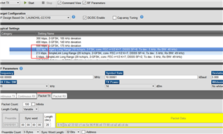
According to the file comparison of the smartrf_settings.c files generated by each airspeed, he had modified the different parameters, but found that the communication still could not be communicated after the modification.

He needed to know the parameters in the generated smartrf_settings.c before which step of the main function called, and how to modify and switch parameters. The figure below is a screenshot of some of the modified parameters, as well as the modified statement before RF initialization.

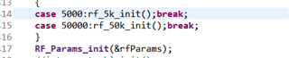
What's more, using the search function, customer can't see where the parameters of smartrf_setting.c are assigned.

Could you help check this case? Thanks.

Best Regards,                                                        

Nick

  • I am not sure I understand the figures you are showing or what the actual problem is.

    If the customer wants to use both the legacy lrm (625 bps) and the SimpleLink lrm (5 kbps) he needs to include all the settings/overrides/patches for both mode in his smartrf_settings files:

    //*********************************************************************************
    // Parameter summary
    // RX Address0: 0xAA 
    // RX Address1: 0xBB 
    // RX Address Mode: No address check 
    // Frequency: 868.00000 MHz
    // Data Format: Serial mode disable 
    // Deviation: 5.000 kHz
    // Packet Length Config: Variable 
    // Max Packet Length: 255 
    // Packet Length: 20 
    // Packet Data: 255 
    // RX Filter BW: 39 kHz
    // Symbol Rate: 10.00061 kBaud
    // Sync Word Length: 32 Bits 
    // TX Power: 14 dBm (requires define CCFG_FORCE_VDDR_HH = 1 in ccfg.c, see CC13xx/CC26xx Technical Reference Manual)
    // Whitening: No whitening 
    
    #include "smartrf_settings.h"
    
    #include DeviceFamily_constructPath(rf_patches/rf_patch_cpe_lrm.h)
    #include DeviceFamily_constructPath(rf_patches/rf_patch_rfe_lrm.h)
    
    // TI-RTOS RF Mode Object
    RF_Mode RF_prop =
    {
        .rfMode = RF_MODE_PROPRIETARY_SUB_1,
        .cpePatchFxn = &rf_patch_cpe_lrm,
        .mcePatchFxn = 0,
        .rfePatchFxn = &rf_patch_rfe_lrm
    };
    
    
    // Overrides for CMD_PROP_RADIO_DIV_SETUP
    uint32_t pOverrides_625[] =
    {
        // override_use_patch_prop_lrm.xml
        // PHY: Use MCE ROM bank 3, RFE RAM patch
        MCE_RFE_OVERRIDE(0,3,0,1,0,0),
        // override_synth_prop_863_930_div5.xml
        // Synth: Set recommended RTRIM to 7
        .
        .
        .
        (uint32_t)0xFFFFFFFF
    };
    
    
    // CMD_PROP_RADIO_DIV_SETUP
    // Proprietary Mode Radio Setup Command for All Frequency Bands
    rfc_CMD_PROP_RADIO_DIV_SETUP_t RF_cmdPropRadioDivSetup_625 =
    {
        .commandNo = 0x3807,
        .status = 0x0000,
        .pNextOp = 0, // INSERT APPLICABLE POINTER: (uint8_t*)&xxx
        .startTime = 0x00000000,
        .
        .
        .
        .pRegOverride = pOverrides_625,
        .centerFreq = 0x0364,
        .intFreq = 0x8000,
        .loDivider = 0x05
    };
    
    
    // CMD_FS
    // Frequency Synthesizer Programming Command
    rfc_CMD_FS_t RF_cmdFs_625 =
    {
        .commandNo = 0x0803,
        .status = 0x0000,
        .pNextOp = 0, // INSERT APPLICABLE POINTER: (uint8_t*)&xxx
        .
        .
    };
    
    
    // CMD_PROP_TX
    // Proprietary Mode Transmit Command
    rfc_CMD_PROP_TX_t RF_cmdPropTx_625 =
    {
        .commandNo = 0x3801,
        .status = 0x0000,
        .pNextOp = 0, // INSERT APPLICABLE POINTER: (uint8_t*)&xxx
       .
       .
       .
    };
    
    
    // CMD_PROP_RX
    // Proprietary Mode Receive Command
    rfc_CMD_PROP_RX_t RF_cmdPropRx_625 =
    {
        .commandNo = 0x3802,
        .status = 0x0000,
        .pNextOp = 0, // INSERT APPLICABLE POINTER: (uint8_t*)&xxx
        .startTime = 0x00000000,
       .
       .
       .
    };
    
    
    //*********************************************************************************
    // Parameter summary
    // RX Address0: 0xAA 
    // RX Address1: 0xBB 
    // RX Address Mode: No address check 
    // Frequency: 868.00000 MHz
    // Data Format: Serial mode disable 
    // Deviation: 5.000 kHz
    // Packet Length Config: Variable 
    // Max Packet Length: 255 
    // Packet Length: 20 
    // Packet Data: 255 
    // RX Filter BW: 49 kHz
    // Symbol Rate: 19.99969 kBaud
    // Sync Word Length: 32 Bits 
    // TX Power: 14 dBm (requires define CCFG_FORCE_VDDR_HH = 1 in ccfg.c, see CC13xx/CC26xx Technical Reference Manual)
    // Whitening: CC1101/CC2500 compatible 
    
    #include "smartrf_settings.h"
    
    #include DeviceFamily_constructPath(rf_patches/rf_patch_cpe_sl_longrange.h)
    #include DeviceFamily_constructPath(rf_patches/rf_patch_rfe_sl_longrange.h)
    #include DeviceFamily_constructPath(rf_patches/rf_patch_mce_sl_longrange.h)
    
    // TI-RTOS RF Mode Object
    RF_Mode RF_prop =
    {
        .rfMode = RF_MODE_PROPRIETARY_SUB_1,
        .cpePatchFxn = &rf_patch_cpe_sl_longrange,
        .mcePatchFxn = &rf_patch_mce_sl_longrange,
        .rfePatchFxn = &rf_patch_rfe_sl_longrange
    };
    
    
    // Overrides for CMD_PROP_RADIO_DIV_SETUP
    uint32_t pOverrides_5k[] =
    {
        // override_use_patch_simplelink_long_range.xml
        // PHY: Use MCE RAM patch, RFE RAM patch
        MCE_RFE_OVERRIDE(1,0,0,1,0,0),
        // override_synth_prop_863_930_div5_lbw60k.xml
        // Synth: Set recommended RTRIM to 7
        HW_REG_OVERRIDE(0x4038,0x0037),
        .
        .
        .
        (uint32_t)0xFFFFFFFF
    };
    
    
    // CMD_PROP_RADIO_DIV_SETUP
    // Proprietary Mode Radio Setup Command for All Frequency Bands
    rfc_CMD_PROP_RADIO_DIV_SETUP_t RF_cmdPropRadioDivSetup_5k =
    {
        .commandNo = 0x3807,
        .status = 0x0000,
        .pNextOp = 0, // INSERT APPLICABLE POINTER: (uint8_t*)&xxx
        .startTime = 0x00000000,
        .
        .
        .
        .pRegOverride = pOverrides_5k,
        .centerFreq = 0x0364,
        .intFreq = 0x8000,
        .loDivider = 0x05
    };
    
    
    // CMD_FS
    // Frequency Synthesizer Programming Command
    rfc_CMD_FS_t RF_cmdFs_5k =
    {
        .commandNo = 0x0803,
        .status = 0x0000,
        .pNextOp = 0, // INSERT APPLICABLE POINTER: (uint8_t*)&xxx
        .startTime = 0x00000000,
        .startTrigger.triggerType = 0x0,
        .
        .
        .
    };
    
    
    // CMD_PROP_TX
    // Proprietary Mode Transmit Command
    rfc_CMD_PROP_TX_t RF_cmdPropTx_5k =
    {
        .commandNo = 0x3801,
        .status = 0x0000,
        .pNextOp = 0, // INSERT APPLICABLE POINTER: (uint8_t*)&xxx
        .
        .
        .
    };
    
    
    // CMD_PROP_RX
    // Proprietary Mode Receive Command
    rfc_CMD_PROP_RX_t RF_cmdPropRx_5k =
    {
        .commandNo = 0x3802,
        .status = 0x0000,
        .pNextOp = 0, // INSERT APPLICABLE POINTER: (uint8_t*)&xxx
       .
       .
       .
    };


    To change between the PHYs, you can simply open the RF driver with one PHY, do whatever you want, close the driver, and then open it up again with the other PHY.

    The code export in Smartrf Studio will only give you one PHY at the time, so you first have to export one PHY, rename it, then export the other one, and paste the settings into the first file (or you can have two different SmartRF_settings files in your code, with different names for the different PHYs.

    Siri