


Hi TI Teams:
The mode I use is synchronous serial Mode, 9600bps air baud rate can be transmitted and receivered normally, but 19200bps air baud rate can only be receivered , and TX is not correct. I use an oscilloscope to measure TX_ RX_ CLK waveform, found that the rate waveform is incorrect,The waveform of TX_ DATA is also wrong My configuration IOCFG3=0X08, IOCFG2=0X09, IOCFG1=0XB0, IOCFG0=0X30.9600bps and 19200bps switching is SYMBOL_ The RATE 1/2/3 is different from the frequency offset. Everything else is the same. Thank you.
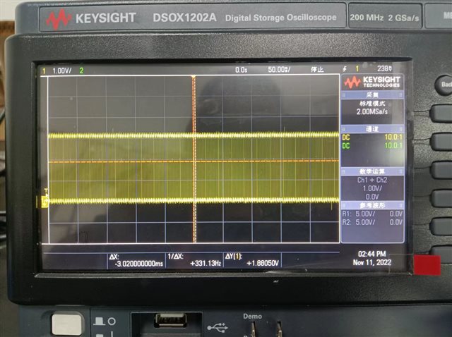
Below is the my SCH and waveforms,CLK is 330KHz and no DATA waveforms.


static const registerSetting_t registerSettings[]=
{
    {CC112X_IOCFG3, 0x08},
    {CC112X_IOCFG2, 0x09},
    {CC112X_IOCFG1, 0xB0},
    {CC112X_IOCFG0, 0x30},
    {CC112X_SYNC3,  0xCC},
    {CC112X_SYNC2,  0xCC},
    {CC112X_SYNC1,  0xCC},
    {CC112X_SYNC0,  0xCC},
    {CC112X_SYNC_CFG1, 0x0B},
    {CC112X_SYNC_CFG0, 0x17},
    {CC112X_DEVIATION_M, 0x70}, // Frequency Deviation
    {CC112X_MODCFG_DEV_E, 0x0A},
    {CC112X_DCFILT_CFG,  0x56},
    {CC112X_PREAMBLE_CFG1, 0x00},
    {CC112X_PREAMBLE_CFG0, 0x35},
    {CC112X_FREQ_IF_CFG, 0x31},
    {CC112X_IQIC, 0xCE},
    {CC112X_CHAN_BW, 0x0D},// RX Filter BW
    {CC112X_MDMCFG1, 0x06},
    //{CC112X_MDMCFG0, 0x0A}, //RX
    {CC112X_MDMCFG0, 0x05},  //TX
    {CC112X_SYMBOL_RATE2, 0x7F},
    {CC112X_SYMBOL_RATE1, 0x75},
    {CC112X_SYMBOL_RATE0, 0x10},
   // {CC112X_AGC_REF,      0x20},
    {CC112X_AGC_CS_THR, 0xEA},
    //{CC112X_AGC_CFG1, 0x0A}, //RX
    {CC112X_AGC_CFG1, 0x2D}, //TX
    {CC112X_AGC_CFG0, 0x5F},
    {CC112X_FIFO_CFG, 0x00},
    {CC112X_FS_CFG, 0x14},
    {CC112X_PKT_CFG2, 0x05},
    {CC112X_PKT_CFG1, 0x00},
    {CC112X_PKT_CFG0, 0x20},
    {CC112X_PA_CFG2, 0x5D},
    {CC112X_PA_CFG0, 0x7E},//PA = 0dBm
    {CC112X_IF_MIX_CFG, 0x00},
    {CC112X_FREQOFF_CFG, 0x22}, //rx
    //{CC112X_FREQOFF_CFG, 0x24}, //Tx
    {CC112X_FREQ2, 0x5A},
    {CC112X_FREQ1, 0x5F},
    {CC112X_FREQ0, 0x5C},
    {CC112X_IF_ADC0, 0x05},
    {CC112X_FS_DIG1, 0x00},
    {CC112X_FS_DIG0, 0x5F},
    {CC112X_FS_CAL0, 0x0E},
    {CC112X_FS_DIVTWO, 0x03},
    {CC112X_FS_DSM0, 0x33},
    {CC112X_FS_DVC0, 0x17},
    {CC112X_FS_PFD, 0x50},
    {CC112X_FS_PRE, 0x6E},
    {CC112X_FS_REG_DIV_CML, 0x14},
    {CC112X_FS_SPARE, 0xAC},
    {CC112X_XOSC5, 0x0E},
    {CC112X_XOSC3, 0xC7},
    {CC112X_XOSC1, 0x07},
    {CC112X_SERIAL_STATUS, 0x08},
};
void Init_CC112x_TX()
{
       uint8_t writeByte;
      //Set serial mode specific registers
      writeByte = 0x08;
      cc112xSpiWriteReg(CC112X_IOCFG3, &writeByte, 1);
      writeByte = 0xb0;
      cc112xSpiWriteReg(CC112X_IOCFG2, &writeByte, 1);
      writeByte = 0x30;
      cc112xSpiWriteReg(CC112X_IOCFG0, &writeByte, 1);
      writeByte = 0x08;
      cc112xSpiWriteReg(CC112X_SYNC_CFG1, &writeByte, 1);
      writeByte = 0x00;
      cc112xSpiWriteReg(CC112X_PREAMBLE_CFG1, &writeByte, 1);
      writeByte = 0x06;
      cc112xSpiWriteReg(CC112X_MDMCFG1, &writeByte, 1);
      writeByte = 0x05;
      cc112xSpiWriteReg(CC112X_MDMCFG0, &writeByte, 1);
      writeByte = 0x2D;
      cc112xSpiWriteReg(CC112X_AGC_CFG1, &writeByte, 1);
      writeByte = 0x05;
      cc112xSpiWriteReg(CC112X_PKT_CFG2, &writeByte, 1);
      writeByte = 0x00;
      cc112xSpiWriteReg(CC112X_PKT_CFG1, &writeByte, 1);
      writeByte = 0x08;
      cc112xSpiWriteReg(CC112X_SERIAL_STATUS, &writeByte, 1);

}
void Init_CC112x_RX()
{
      uint8_t writeByte;
      //Set serial mode specific registers
      writeByte = 0x08;
      cc112xSpiWriteReg(CC112X_IOCFG3, &writeByte, 1);
      writeByte = 0x09;
      cc112xSpiWriteReg(CC112X_IOCFG2, &writeByte, 1);
      writeByte = 0xb0;
      cc112xSpiWriteReg(CC112X_IOCFG0, &writeByte, 1);
      writeByte = 0x1F;
      cc112xSpiWriteReg(CC112X_SYNC_CFG1, &writeByte, 1);
      writeByte = 0x00;
      cc112xSpiWriteReg(CC112X_PREAMBLE_CFG1, &writeByte, 1);
      writeByte = 0x06;
      cc112xSpiWriteReg(CC112X_MDMCFG1, &writeByte, 1);
      writeByte = 0x0A;
      cc112xSpiWriteReg(CC112X_MDMCFG0, &writeByte, 1);
      writeByte = 0x0A;
      cc112xSpiWriteReg(CC112X_AGC_CFG1, &writeByte, 1);
      writeByte = 0x05;
      cc112xSpiWriteReg(CC112X_PKT_CFG2, &writeByte, 1);
      writeByte = 0x00;
      cc112xSpiWriteReg(CC112X_PKT_CFG1, &writeByte, 1);
      writeByte = 0x08;
      cc112xSpiWriteReg(CC112X_SERIAL_STATUS, &writeByte, 1);
}
void CC112x_19200()
{
       uint8_t writeByte;

       writeByte = 0xA3; //4K
       cc112xSpiWriteReg(CC112X_DEVIATION_M, &writeByte, 1);
       writeByte = 0x0A;
       cc112xSpiWriteReg(CC112X_MODCFG_DEV_E, &writeByte, 1);

       writeByte = 0x4E; //IQ image compensation disabled
       cc112xSpiWriteReg(CC112X_IQIC, &writeByte, 1);
       writeByte = 0x06; //CHAN_BW 41.7 20
       cc112xSpiWriteReg(CC112X_CHAN_BW, &writeByte, 1);

       writeByte = 0x7F; //19.2KHz
       cc112xSpiWriteReg(CC112X_SYMBOL_RATE2, &writeByte, 1);
       writeByte = 0x75;
       cc112xSpiWriteReg(CC112X_SYMBOL_RATE1, &writeByte, 1);
       writeByte = 0x10;
       cc112xSpiWriteReg(CC112X_SYMBOL_RATE0, &writeByte, 1);

}
void CC112x_9600()
{
       uint8_t writeByte;

       writeByte = 0xF7; //2.4k
       cc112xSpiWriteReg(CC112X_DEVIATION_M, &writeByte, 1);
       writeByte = 0x09;
       cc112xSpiWriteReg(CC112X_MODCFG_DEV_E, &writeByte, 1);

       writeByte = 0xCE; //IQ image compensation disabled
       cc112xSpiWriteReg(CC112X_IQIC, &writeByte, 1);
       writeByte = 0x0D; //CHAN_BW 19.2  20
       cc112xSpiWriteReg(CC112X_CHAN_BW, &writeByte, 1);

       writeByte = 0x6F; //9.6KBPS
       cc112xSpiWriteReg(CC112X_SYMBOL_RATE2, &writeByte, 1);
       writeByte = 0x75;
       cc112xSpiWriteReg(CC112X_SYMBOL_RATE1, &writeByte, 1);
       writeByte = 0x10;
       cc112xSpiWriteReg(CC112X_SYMBOL_RATE0, &writeByte, 1);

}

void Air_Rate_Init() //
{
	Radio_Para.Wireless_Link_Rate = Memory_Content[2];
	switch(Radio_Para.Wireless_Link_Rate)
	{
		case '4':
		CC112x_19200();
		break;
		case '2':
		CC112x_9600();
		break;
		default:
		Radio_Para.Wireless_Link_Rate = '2';
		CC112x_9600();;
		break;
	}
}
void Exti_Init()
{
   /* TRX_SCK*/
    GPIO_MODER(RADIO_TRX_CLK_PORT,RADIO_TRX_CLK_PIN,0);//PA8
    GPIO_Speed(RADIO_TRX_CLK_PORT,RADIO_TRX_CLK_PIN,3);//50MHz
    GPIO_Pull_Up_Down(RADIO_TRX_CLK_PORT,RADIO_TRX_CLK_PIN,0);

    SYSCFG_EXTILineConfig(0,8);

    if(Radio_Para.Operating_Mode == '2')  //RX
    {
          Ex_NVIC_Config(0,8,1);//PA8 FALLING
    }
    else if(Radio_Para.Operating_Mode == '0') //TX
    {
         Ex_NVIC_Config(0,8,2);//PA8 RISE
    }

    NVIC_Init(0,2,EXTI9_5_IRQn,2);

}
void InitCC112x()
{
      uint8_t writeByte;
      trxSpiCmdStrobe(CC112X_SRES); // Reset radio
      for(uint16_t i = 0; i < (sizeof(registerSettings)/sizeof(registerSetting_t)); i++)
      {
          writeByte =registerSettings[i].data;
          cc112xSpiWriteReg( registerSettings[i].addr, &writeByte, 1);
      }
      cc112xSpiReadReg(CC112X_IOCFG3, &writeByte, 1);
      if(writeByte !=registerSettings[0].data)while(1);
      trxSpiCmdStrobe(CC112X_SCAL);
      //cc112xSpiReadReg(CC112X_PARTNUMBER, &writeByte, 1);
      //if(writeByte!=0x58)while(1);
}

void Init_Radio()//TX
{
	Init_Sys();
    InitCC112x();
    ManualCalibration();
    Air_Rate_Init();
	Init_CC112x_TX();
    Exti_Init();
}

