Other Parts Discussed in Thread: CC1101, , CC430F5137
Hi team,
Here's the request from the customer:
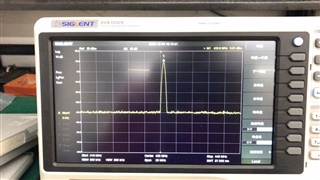
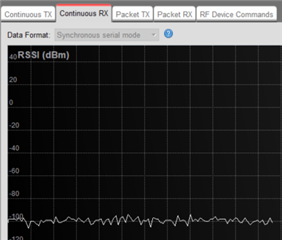
One phenomenon has been found in the current test, the CC1310 doing RF reception, the CC1101 or the CC430 doing RF transmission (gain is 5 dBm). The effective communication distance between them is only a little over 5 meters.
But one CC1310RF receive, another CC1310 transmit, or one C1101, CC430RF receive, the other uses C1101 and CC430 for RF transmission, and their effective communication distance can reach around 35-40 meters.
I would like to know that the CC1310 needs to be compatible with both the C1101 and CC430 products. Both the old and new products have been whitening and no Manchester encoding. What configuration needs to be modified? Can you specify that?
The question is about the CC1310 is too short to the CC1101, or the CC1310 is too short to the CC430. The communication distance between CC1310 and CC1310 or CC430 and CC1101 is normal.
This is the CC430RF parameter:
0x08, // FSCTRL1 Frequency synthesizer control.
0x00, // FSCTRL0 Frequency synthesizer control.
0x10, // FREQ2 Frequency control word, high byte.
0x9D, // FREQ1 Frequency control word, middle byte.
0x89, // FREQ0 Frequency control word, low byte.

0x7A, // MDMCFG4 Modem configuration.
0x83, // MDMCFG3 Modem configuration.
0x13, // MDMCFG2 Modem configuration.

0x22, // MDMCFG1 Modem configuration.
0xF8, // MDMCFG0 Modem configuration.

0x05, // CHANNR Channel number.
0x42, // DEVIATN Modem deviation setting (when FSK modulation is enabled).

0xB6, // FREND1 Front end RX configuration.
0x10, // FREND0 Front end TX configuration.
0x18, // MCSM0 Main Radio Control State Machine configuration.//18
0x1D, // FOCCFG Frequency Offset Compensation Configuration.
0x1C, // BSCFG Bit synchronization Configuration.
0xc7, // AGCCTRL2 AGC control.
0x00, // AGCCTRL1 AGC control.
0xb2, // AGCCTRL0 AGC control.
0xEA, // FSCAL3 Frequency synthesizer calibration.
0x2A, // FSCAL2 Frequency synthesizer calibration.
0x00, // FSCAL1 Frequency synthesizer calibration.
0x1F, // FSCAL0 Frequency synthesizer calibration.
0x59, // FSTEST Frequency synthesizer calibration.
0x81, // TEST2 Various test settings.
0x35, // TEST1 Various test settings.
0x09, // TEST0 Various test settings.
0x47, // FIFOTHR RXFIFO and TXFIFO thresholds.
0x06, // IOCFG2 GDO2 output pin configuration.
0x06, // IOCFG0 GDO0 output pin configuration. Refer to SmartRF?Studio User Manual for detailed pseudo register explanation.
0x04, // PKTCTRL1 Packet automation control.
0x45, // PKTCTRL0 Packet automation control.
0x00, // ADDR Device address.
0x3D, // PKTLEN Packet length.
This is the CC1310RF parameter:// CMD_PROP_RADIO_DIV_SETUP
rfc_CMD_PROP_RADIO_DIV_SETUP_t RF_cmdPropRadioDivSetup =
{
.commandNo = 0x3807,
.status = 0x0000,
.pNextOp = 0, // INSERT APPLICABLE POINTER: (uint8_t*)&xxx
.startTime = 0x00000000,
.startTrigger.triggerType = 0x0,
.startTrigger.bEnaCmd = 0x0,
.startTrigger.triggerNo = 0x0,
.startTrigger.pastTrig = 0x0,
.condition.rule = 0x0, //0x1,
.condition.nSkip = 0x0,
.modulation.modType = 0x1,
.modulation.deviation = 0x64,
.symbolRate.preScale = 0xF,
.symbolRate.rateWord = 0x624E,
.symbolRate.decimMode = 0x0,
.rxBw = 0x25,
.preamConf.nPreamBytes = 0x4,
.preamConf.preamMode = 0x0,
.formatConf.nSwBits = 0x20,
.formatConf.bBitReversal = 0x0,
.formatConf.bMsbFirst = 0x1,
.formatConf.fecMode = 0x0,
.formatConf.whitenMode = 0x1,
.config.frontEndMode = 0x0,
.config.biasMode = 0x1,
.config.analogCfgMode = 0x0,
.config.bNoFsPowerUp = 0x0,
// .txPower = 0x913F, //15dBm
// .txPower = 0xD80F, //13dBm
.txPower = 0x46CB, //10dBm
.pRegOverride = pOverrides,
.centerFreq = 0x01B1,
.intFreq = 0x8000,
.loDivider = 0x0A,
};
// CMD_FS
rfc_CMD_FS_t RF_cmdFs =
{
.commandNo = 0x0803,
.status = 0x0000,
.pNextOp = 0, // INSERT APPLICABLE POINTER: (uint8_t*)&xxx
.startTime = 0x00000000,
.startTrigger.triggerType = 0x0,
.startTrigger.bEnaCmd = 0x0,
.startTrigger.triggerNo = 0x0,
.startTrigger.pastTrig = 0x0,
.condition.rule = 0x0, //0x1,
.condition.nSkip = 0x0,
.frequency = 0x01B1,
// .fractFreq = 0x0000,//433
.fractFreq = 0x3334, //433.2
// .fractFreq = 0x6667, //433.4
// .fractFreq = 0x999A, //433.6
.synthConf.bTxMode = 0x0,
.synthConf.refFreq = 0x0,
.__dummy0 = 0x00,
.__dummy1 = 0x00,
.__dummy2 = 0x00,
.__dummy3 = 0x0000,
};
// CMD_PROP_TX
rfc_CMD_PROP_TX_t RF_cmdPropTx =
{
.commandNo = 0x3801,
.status = 0x0000,
.pNextOp = 0, // INSERT APPLICABLE POINTER: (uint8_t*)&xxx
.startTime = 0x00000000,
.startTrigger.triggerType = 0x0,
.startTrigger.bEnaCmd = 0x0,
.startTrigger.triggerNo = 0x0,
.startTrigger.pastTrig = 0x0,
.condition.rule = 0x0, //0x1,
.condition.nSkip = 0x0,
.pktConf.bFsOff = 0x0,
.pktConf.bUseCrc = 0x1,
.pktConf.bVarLen = 0x1,
.pktLen = 0x1E, // SET APPLICATION PAYLOAD LENGTH
.syncWord = 0xD391D391,
.pPkt = 0, // INSERT APPLICABLE POINTER: (uint8_t*)&xxx
};
// CMD_PROP_RX
rfc_CMD_PROP_RX_t RF_cmdPropRx =
{
.commandNo = 0x3802,
.status = 0x0000,
.pNextOp = 0, // INSERT APPLICABLE POINTER: (uint8_t*)&xxx
.startTime = 0x00000000,
.startTrigger.triggerType = 0x0,
.startTrigger.bEnaCmd = 0x0,
.startTrigger.triggerNo = 0x0,
.startTrigger.pastTrig = 0x0,
.condition.rule = 0x0, //0x1,
.condition.nSkip = 0x0,
.pktConf.bFsOff = 0x0,
.pktConf.bRepeatOk = 0x0,
.pktConf.bRepeatNok = 0x0,
.pktConf.bUseCrc = 0x1,
.pktConf.bVarLen = 0x1,
.pktConf.bChkAddress = 0x0,
.pktConf.endType = 0x0,
.pktConf.filterOp = 0x0,
.rxConf.bAutoFlushIgnored = 0x0,
.rxConf.bAutoFlushCrcErr = 0x0,
.rxConf.bIncludeHdr = 0x1,
.rxConf.bIncludeCrc = 0x0,
.rxConf.bAppendRssi = 0x0,
.rxConf.bAppendTimestamp = 0x0,
.rxConf.bAppendStatus = 0x1,
.syncWord = 0xD391D391,
.maxPktLen = 0x80, // MAKE SURE DATA ENTRY IS LARGE ENOUGH
.address0 = 0xAA,
.address1 = 0xBB,
.endTrigger.triggerType = 0x1,
.endTrigger.bEnaCmd = 0x0,
.endTrigger.triggerNo = 0x0,
.endTrigger.pastTrig = 0x0,
.endTime = 0x00000000,
.pQueue = 0, // INSERT APPLICABLE POINTER: (dataQueue_t*)&xxx
.pOutput = 0, // INSERT APPLICABLE POINTER: (uint8_t*)&xxx
};
Could you help check this case? Thanks.
Best Regards,
Nick