This thread has been locked.

If you have a related question, please click the "Ask a related question" button in the top right corner. The newly created question will be automatically linked to this question.

CC1310: Some issues about cc1310+sky65115.

Part Number: CC1310


Hi team,

Here's the request from the customer:

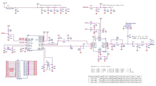
Customer uses the cc1310+sky65115 circuit officially recommended and the official gerber file of TI to print and test. 

Issue 1. SmartRF Studio 7 receives a maximum signal strength of -21db.

Issue 2. Using frequency 470Mhz single-ended transceiver mode, the distance is only about 500 meters outside.

  1. Customer doesn’t know why the input signal SmartRF Studio 7 shows the strongest -21db, even if the 1db signal is directly injected into the cc1310 FR-N or FR-P pin through the signal line, the display signal is only -21db, the schematic diagram is as follows.
  2. Why is the CRC error even when the outdoor distance is very short, only 500 meters?
  3. Is the setting of 470M single-ended mode correct?

Indoor test condition (left receive, right transmit):

Transmit Signal Strength:

Received signal strength:

Outdoor test condition (about 872 meters, actual straight line distance is about 500 meters.):

Pcb board (Sheet thickness 0.8mm material FR-4) :

Customers have commonly used tools such as spectrometers and network analyzers, shielded boxes, etc. Where and how should they test and check?

They want to figure out the actual transmission distance before designing their own products

Could you help check this case? Thanks.

Best Regards,                                                        

Nick

  • Hi Nick,

    If the design is unchanged from the TI reference design then it's best to first look at the settings being used.

    • Has the customer followed all of the setup instructions in SWRA528 (CC1310 Skyworks 433MHz PA Reference Design): https://www.ti.com/lit/swra528?
    • It looks like they have set the frontEndMode to the correct setting (Config.frontEndMode = 0x02: Single-ended mode RFN), but are not setting biasMode to use an external bias for the LNA (config.biasMode = 1: External bias) - instructions are given in Section 2.4.2.
    • Is the truth table to configure the SKY65115 in RX mode being done in SmartRF Studio? 

      More specifically, are the correct IO signals being set using Settings -> Custom Target Configuration -> Setting the correct I/O signals high/low for TX/RX for the SKY65115? Details are given in Section 2.4.1.
    • If following the Apps Note does not improve performance, could the customer export the settings they are using in SmartRF Studio (for TX and RX) and upload the attachment (rather than copy/pasting into a post)? 

    Regards,
    Zack