This thread has been locked.

If you have a related question, please click the "Ask a related question" button in the top right corner. The newly created question will be automatically linked to this question.

LP-CC1352P7: Issues using the upper range of 902-928 MHz with proprietary RF

Part Number: LP-CC1352P7
Other Parts Discussed in Thread: SYSCONFIG

Is there a unique PHY setting for using the upper end of the 902-928 MHz range? 
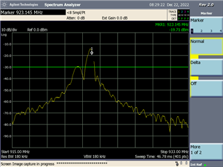
Mine seems to be falling apart > 920 MHz. I've attached SA traces of 919 MHz and 923 MHz 

I tried 2 custom PHYs. 
- 1 Mbps dialed down to 500 kbps
- 50 kbps dialed up to 500 kbps with increased deviation and RX bandwidth. 

They both fell apart around 920 MHz when sweeping upward
Just wondering if there's a specific PHY setting I need to use this ~8 MHz of spectrum. 

Thanks

  • Hi Mike,

    Could you share the exact settings you used for each PHY?

  • Thanks Diego

    Here's the primary one I'm using. 
    In Proprietary 779-930 MHz, selected 1 Mbps, 350 kHz deviation 2 GFSK, 2.2. MHz Rx BW.
    Then I changed the baud rate down to 500 kbps. Everything else is the same. 

    This is the code I'm using to set frequency, which works anywhere from 902-920 MHz.

    void radio_set_freq(double f) {

        rf_ctx.RF_cmdFs->frequency = (uint16_t)f;

        rf_ctx.RF_cmdPropRadioDivSetup->centerFreq = (uint16_t)f;

        rf_ctx.RF_cmdFs->fractFreq = 65536*(f - (uint16_t)f);

        /* Set the frequency. Now the RF driver powers the RF core up and runs the setup command from above.

         * The FS command is executed and also cached for later use when the RF driver does an automatic

         * power up. */

        RF_EventMask result = RF_runCmd(rfHandle, (RF_Op*)rf_ctx.RF_cmdFs, RF_PriorityNormal, NULL, 0);

        if ((result != RF_EventLastCmdDone) || ((volatile RF_Op*)rf_ctx.RF_cmdFs)->status != DONE_OK)

        {

            while(1);

        }

    }

    Here is my radio config

    /*

     *  ======== ti_radio_config.c ========

     *  Configured RadioConfig module definitions

     *

     *  DO NOT EDIT - This file is generated for the CC1352P7RGZ

     *  by the SysConfig tool.

     *

     *  Radio Config module version : 1.14

     *  SmartRF Studio data version : 2.27.0

     */

    #include "ti_radio_config.h"

    #include DeviceFamily_constructPath(rf_patches/rf_patch_cpe_prop.h)

    // *********************************************************************************

    //   RF Frontend configuration

    // *********************************************************************************

    // RF design based on: LP_CC1352P7-1

    // TX Power tables

    // The RF_TxPowerTable_DEFAULT_PA_ENTRY and RF_TxPowerTable_HIGH_PA_ENTRY macros are defined in RF.h.

    // The following arguments are required:

    // RF_TxPowerTable_DEFAULT_PA_ENTRY(bias, gain, boost, coefficient)

    // RF_TxPowerTable_HIGH_PA_ENTRY(bias, ibboost, boost, coefficient, ldoTrim)

    // See the Technical Reference Manual for further details about the "txPower" Command field.

    // The PA settings require the CCFG_FORCE_VDDR_HH = 0 unless stated otherwise.

    // 868 MHz, 13 dBm

    RF_TxPowerTable_Entry txPowerTable_868_pa13[TXPOWERTABLE_868_PA13_SIZE] =

    {

        {-20, RF_TxPowerTable_DEFAULT_PA_ENTRY(0, 3, 0, 2) }, // 0x04C0

        {-15, RF_TxPowerTable_DEFAULT_PA_ENTRY(1, 3, 0, 3) }, // 0x06C1

        {-10, RF_TxPowerTable_DEFAULT_PA_ENTRY(2, 3, 0, 5) }, // 0x0AC2

        {-5, RF_TxPowerTable_DEFAULT_PA_ENTRY(4, 3, 0, 5) }, // 0x0AC4

        {0, RF_TxPowerTable_DEFAULT_PA_ENTRY(8, 3, 0, 8) }, // 0x10C8

        {1, RF_TxPowerTable_DEFAULT_PA_ENTRY(9, 3, 0, 9) }, // 0x12C9

        {2, RF_TxPowerTable_DEFAULT_PA_ENTRY(10, 3, 0, 9) }, // 0x12CA

        {3, RF_TxPowerTable_DEFAULT_PA_ENTRY(11, 3, 0, 10) }, // 0x14CB

        {4, RF_TxPowerTable_DEFAULT_PA_ENTRY(13, 3, 0, 11) }, // 0x16CD

        {5, RF_TxPowerTable_DEFAULT_PA_ENTRY(14, 3, 0, 14) }, // 0x1CCE

        {6, RF_TxPowerTable_DEFAULT_PA_ENTRY(17, 3, 0, 16) }, // 0x20D1

        {7, RF_TxPowerTable_DEFAULT_PA_ENTRY(20, 3, 0, 19) }, // 0x26D4

        {8, RF_TxPowerTable_DEFAULT_PA_ENTRY(24, 3, 0, 22) }, // 0x2CD8

        {9, RF_TxPowerTable_DEFAULT_PA_ENTRY(28, 3, 0, 31) }, // 0x3EDC

        {10, RF_TxPowerTable_DEFAULT_PA_ENTRY(18, 2, 0, 31) }, // 0x3E92

        {11, RF_TxPowerTable_DEFAULT_PA_ENTRY(26, 2, 0, 51) }, // 0x669A

        {12, RF_TxPowerTable_DEFAULT_PA_ENTRY(30, 1, 1, 68) }, // 0x895E

        // The original PA value (12.5 dBm) has been rounded to an integer value.

        {13, RF_TxPowerTable_DEFAULT_PA_ENTRY(36, 0, 0, 89) }, // 0xB224

        // This setting requires CCFG_FORCE_VDDR_HH = 1.

        {14, RF_TxPowerTable_DEFAULT_PA_ENTRY(63, 0, 1, 0) }, // 0x013F

        RF_TxPowerTable_TERMINATION_ENTRY

    };

    // 868 MHz, 20 dBm

    RF_TxPowerTable_Entry txPowerTable_868_pa20[TXPOWERTABLE_868_PA20_SIZE] =

    {

        {14, RF_TxPowerTable_HIGH_PA_ENTRY(13, 0, 0, 28, 0) }, // 0x00380D

        {15, RF_TxPowerTable_HIGH_PA_ENTRY(18, 0, 0, 36, 0) }, // 0x004812

        {16, RF_TxPowerTable_HIGH_PA_ENTRY(24, 0, 0, 43, 0) }, // 0x005618

        {17, RF_TxPowerTable_HIGH_PA_ENTRY(28, 0, 0, 51, 2) }, // 0x02661C

        {18, RF_TxPowerTable_HIGH_PA_ENTRY(34, 0, 0, 64, 4) }, // 0x048022

        {19, RF_TxPowerTable_HIGH_PA_ENTRY(15, 3, 0, 36, 4) }, // 0x0448CF

        {20, RF_TxPowerTable_HIGH_PA_ENTRY(18, 3, 0, 71, 27) }, // 0x1B8ED2

        RF_TxPowerTable_TERMINATION_ENTRY

    };

    // 2400 MHz, 5 dBm

    RF_TxPowerTable_Entry txPowerTable_2400_pa5[TXPOWERTABLE_2400_PA5_SIZE] =

    {

        {-20, RF_TxPowerTable_DEFAULT_PA_ENTRY(8, 3, 0, 2) }, // 0x04C8

        {-18, RF_TxPowerTable_DEFAULT_PA_ENTRY(10, 3, 0, 2) }, // 0x04CA

        {-15, RF_TxPowerTable_DEFAULT_PA_ENTRY(13, 3, 0, 3) }, // 0x06CD

        {-12, RF_TxPowerTable_DEFAULT_PA_ENTRY(16, 3, 0, 5) }, // 0x0AD0

        {-10, RF_TxPowerTable_DEFAULT_PA_ENTRY(19, 3, 0, 5) }, // 0x0AD3

        {-9, RF_TxPowerTable_DEFAULT_PA_ENTRY(20, 3, 0, 6) }, // 0x0CD4

        {-6, RF_TxPowerTable_DEFAULT_PA_ENTRY(19, 2, 0, 11) }, // 0x1693

        {-5, RF_TxPowerTable_DEFAULT_PA_ENTRY(21, 2, 0, 11) }, // 0x1695

        {-3, RF_TxPowerTable_DEFAULT_PA_ENTRY(25, 2, 0, 12) }, // 0x1899

        {0, RF_TxPowerTable_DEFAULT_PA_ENTRY(29, 1, 0, 22) }, // 0x2C5D

        {1, RF_TxPowerTable_DEFAULT_PA_ENTRY(33, 1, 0, 25) }, // 0x3261

        {2, RF_TxPowerTable_DEFAULT_PA_ENTRY(38, 1, 0, 31) }, // 0x3E66

        {3, RF_TxPowerTable_DEFAULT_PA_ENTRY(47, 1, 0, 36) }, // 0x486F

        {4, RF_TxPowerTable_DEFAULT_PA_ENTRY(32, 0, 0, 65) }, // 0x8220

        {5, RF_TxPowerTable_DEFAULT_PA_ENTRY(46, 0, 0, 59) }, // 0x762E

        RF_TxPowerTable_TERMINATION_ENTRY

    };

    //*********************************************************************************

    //  RF Setting:   1 Mbps, 350 kHz Deviation, 2-GFSK, 2.2 MHz RX Bandwidth (Pre-Silicon)

    //

    //  PHY:          2gfsk1mbps915

    //  Setting file: setting_tc785.json

    //*********************************************************************************

    // PARAMETER SUMMARY

    // RX Address Mode: No address check

    // Frequency (MHz): 915.0000

    // Deviation (kHz): 350.0

    // Packet Length Config: Variable

    // Max Packet Length: 255

    // Preamble Count: 4 Bytes

    // Preamble Mode: Send 0 as the first preamble bit

    // RX Filter BW (kHz): 2185.1

    // Symbol Rate (kBaud): 500.000

    // Sync Word: 0x930B51DE

    // Sync Word Length: 32 Bits

    // TX Power (dBm): 14

    // Whitening: No whitening

    // TI-RTOS RF Mode Object

    RF_Mode RF_prop_2gfsk1mbps915_0 =

    {

        .rfMode = RF_MODE_AUTO,

        .cpePatchFxn = &rf_patch_cpe_prop,

        .mcePatchFxn = 0,

        .rfePatchFxn = 0

    };

    // Overrides for CMD_PROP_RADIO_DIV_SETUP_PA

    uint32_t pOverrides_2gfsk1mbps915_0[] =

    {

        // override_tc784_tc785.json

        // Tx: Configure PA ramp time, PACTL2.RC=0x3 (in ADI0, set PACTL2[4:3]=0x3)

        ADI_2HALFREG_OVERRIDE(0,16,0x8,0x8,17,0x1,0x1),

        // Rx: Set AGC reference level to 0x2E (default: 0x2E)

        HW_REG_OVERRIDE(0x609C,0x002E),

        // Rx: Set RSSI offset to adjust reported RSSI by -4 dB (default: -2), trimmed for external bias and differential configuration

        (uint32_t)0x000488A3,

        // Set LNA IB offset factor to 0xF

        (uint32_t)0x000F8883,

        // Rx: Set anti-aliasing filter bandwidth to 0x0 (in ADI0, set IFAMPCTL3[7:4]=0xD)

        ADI_HALFREG_OVERRIDE(0,61,0xF,0x0),

        // TX: Reduce analog ramping wait time

        HW_REG_OVERRIDE(0x6028,0x001A),

        // override_prop_common.json

        // DC/DC regulator: In Tx with 14 dBm PA setting, use DCDCCTL5[3:0]=0xF (DITHER_EN=1 and IPEAK=7). In Rx, use default settings.

        (uint32_t)0x00F788D3,

        // override_prop_common_sub1g.json

        // TX: Set FSCA divider bias to 1

        HW32_ARRAY_OVERRIDE(0x405C,0x0001),

        // TX: Set FSCA divider bias to 1

        (uint32_t)0x08141131,

        // override_patable_14dbm.json

        // Tx: Set PA trim to max to maximize its output power (in ADI0, set PACTL0=0xF8)

        ADI_REG_OVERRIDE(0,12,0xF8),

        (uint32_t)0xFFFFFFFF

    };

    // CMD_PROP_RADIO_DIV_SETUP_PA

    // Proprietary Mode Radio Setup Command for All Frequency Bands

    rfc_CMD_PROP_RADIO_DIV_SETUP_PA_t RF_cmdPropRadioDivSetup_2gfsk1mbps915_0 =

    {

        .commandNo = 0x3807,

        .status = 0x0000,

        .pNextOp = 0,

        .startTime = 0x00000000,

        .startTrigger.triggerType = 0x0,

        .startTrigger.bEnaCmd = 0x0,

        .startTrigger.triggerNo = 0x0,

        .startTrigger.pastTrig = 0x0,

        .condition.rule = 0x1,

        .condition.nSkip = 0x0,

        .modulation.modType = 0x1,

        .modulation.deviation = 0x578,

        .modulation.deviationStepSz = 0x0,

        .symbolRate.preScale = 0xF,

        .symbolRate.rateWord = 0x50000,

        .symbolRate.decimMode = 0x0,

        .rxBw = 0x64,

        .preamConf.nPreamBytes = 0x4,

        .preamConf.preamMode = 0x0,

        .formatConf.nSwBits = 0x20,

        .formatConf.bBitReversal = 0x0,

        .formatConf.bMsbFirst = 0x1,

        .formatConf.fecMode = 0x0,

        .formatConf.whitenMode = 0x0,

        .config.frontEndMode = 0x0,

        .config.biasMode = 0x1,

        .config.analogCfgMode = 0x0,

        .config.bNoFsPowerUp = 0x0,

        .config.bSynthNarrowBand = 0x0,

        .txPower = 0x013F,

        .pRegOverride = pOverrides_2gfsk1mbps915_0,

        .centerFreq = 0x0393,

        .intFreq = 0x0D99,

        .loDivider = 0x05,

        .pRegOverrideTxStd = 0,

        .pRegOverrideTx20 = 0

    };

    // CMD_FS

    // Frequency Synthesizer Programming Command

    rfc_CMD_FS_t RF_cmdFs_2gfsk1mbps915_0 =

    {

        .commandNo = 0x0803,

        .status = 0x0000,

        .pNextOp = 0,

        .startTime = 0x00000000,

        .startTrigger.triggerType = 0x0,

        .startTrigger.bEnaCmd = 0x0,

        .startTrigger.triggerNo = 0x0,

        .startTrigger.pastTrig = 0x0,

        .condition.rule = 0x1,

        .condition.nSkip = 0x0,

        .frequency = 0x0393,

        .fractFreq = 0x0000,

        .synthConf.bTxMode = 0x0,

        .synthConf.refFreq = 0x0,

        .__dummy0 = 0x00,

        .__dummy1 = 0x00,

        .__dummy2 = 0x00,

        .__dummy3 = 0x0000

    };

    // CMD_PROP_TX

    // Proprietary Mode Transmit Command

    rfc_CMD_PROP_TX_t RF_cmdPropTx_2gfsk1mbps915_0 =

    {

        .commandNo = 0x3801,

        .status = 0x0000,

        .pNextOp = 0,

        .startTime = 0x00000000,

        .startTrigger.triggerType = 0x0,

        .startTrigger.bEnaCmd = 0x0,

        .startTrigger.triggerNo = 0x0,

        .startTrigger.pastTrig = 0x0,

        .condition.rule = 0x1,

        .condition.nSkip = 0x0,

        .pktConf.bFsOff = 0x0,

        .pktConf.bUseCrc = 0x1,

        .pktConf.bVarLen = 0x1,

        .pktLen = 0x14,

        .syncWord = 0x930B51DE,

        .pPkt = 0

    };

    // CMD_PROP_RX

    // Proprietary Mode Receive Command

    rfc_CMD_PROP_RX_t RF_cmdPropRx_2gfsk1mbps915_0 =

    {

        .commandNo = 0x3802,

        .status = 0x0000,

        .pNextOp = 0,

        .startTime = 0x00000000,

        .startTrigger.triggerType = 0x0,

        .startTrigger.bEnaCmd = 0x0,

        .startTrigger.triggerNo = 0x0,

        .startTrigger.pastTrig = 0x0,

        .condition.rule = 0x1,

        .condition.nSkip = 0x0,

        .pktConf.bFsOff = 0x0,

        .pktConf.bRepeatOk = 0x0,

        .pktConf.bRepeatNok = 0x0,

        .pktConf.bUseCrc = 0x1,

        .pktConf.bVarLen = 0x1,

        .pktConf.bChkAddress = 0x0,

        .pktConf.endType = 0x0,

        .pktConf.filterOp = 0x0,

        .rxConf.bAutoFlushIgnored = 0x0,

        .rxConf.bAutoFlushCrcErr = 0x0,

        .rxConf.bIncludeHdr = 0x1,

        .rxConf.bIncludeCrc = 0x0,

        .rxConf.bAppendRssi = 0x0,

        .rxConf.bAppendTimestamp = 0x0,

        .rxConf.bAppendStatus = 0x1,

        .syncWord = 0x930B51DE,

        .maxPktLen = 0xFF,

        .address0 = 0xAA,

        .address1 = 0xBB,

        .endTrigger.triggerType = 0x1,

        .endTrigger.bEnaCmd = 0x0,

        .endTrigger.triggerNo = 0x0,

        .endTrigger.pastTrig = 0x0,

        .endTime = 0x00000000,

        .pQueue = 0,

        .pOutput = 0

    };

  • Hi Diego - was this enough information? Thanks!

  • Hi Mike,

    I have done some testing and it seems that there is an issue using the 1 Mbps 2-GFSK PHY with the LP-CC1372P7-1 at frequencies at or above 920 MHz.

    If you're intention is to have a data rate of 500 kbps, there is a PHY in SmartRF Studio and sysconfig that supports this data rate. I tested this PHY with SmartRF Studio and I was able to use it at frequencies above 920 MHz.

    This is how it is shown in sysconfig:

    This is how it is shown in SmartRF Studio:

  • Thank you Diego. I'll give it a shot!

  • I need to do quite a bit of surgery to go from rfc_CMD_IEEE_RX_t to rfc_CMD_IEEE_RX_ADV_t . 

    I scratched the surface here a few weeks ago - e2e.ti.com/.../cc1352p7-changing-custom-rf-phy-from-rfsynchronizedpacket-example