This thread has been locked.

If you have a related question, please click the "Ask a related question" button in the top right corner. The newly created question will be automatically linked to this question.

CC1120: Capability of CC11xx in receiving ASK/OOK, transparent mode?

Genius 3985 points
Part Number: CC1120

Hi,

using CC112x for years now in FSK, I wonder why we don't use them outside FSK - we manufacture some thousand (legacy) OOK systems at 868Mhz per year; typical application are keyfob systems.
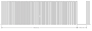
We can't change the protocols of these systems due to backward compatibility; a typical protocol timing is attached!

Today we use good-old TDA receiver chips and I asked my engineers, why they don't use our main RF chip CC11xx.
Reply was 'because you can't use them in ASK transprarent mode':
1. first they obviously can't deal with the long pause in between packet repetitions (we had the same issue with FSK, where at least we tuned the AFC as long as it fits. This doesn't work in ASK, as they told me).
2. then if they tried to use it with much shorter pauses, the sensivity was 20dB worse than with the TDAs

Can you advise if this is correct / how we could use CC's in that field?

thx

  • Hello,

    Transparent mode with ASK modulation is supported.

    A couple of questions:

    Is the payload after the pause the same payload or is it a different payload?

    Could you share more information on how the packet is structured? For example if there is a preamble, sync word, if a 1 and 0 represented by different pulse lengths, pulse length, etc.

    Could you also share the settings that were used in the CC1120 when they tested transparent mode with ASK?

  • Diego, thx. a lot for support,

    the payload is for backward compatibility strange & plain:
    user press a key and TX starts to send simple data packets without any sync/CRC/whatever. Packets are repeated after a max 32ms pause minimum once, sometimes just 'forever' if key remains pressed.
    Coding is done in ancient 1/3 - 2/3 procedure: for example a '0' is represented by (1ms ON" plus 2ms "off"). A "1" means (2ms "ON" and 1ms "OFF") - so there is a return-to-zero every bit.

    Hope that give some some light on the subject.

    I attach CC1120's settings, its just SRF standard

    regards

    Gerhard

    <html><head>
    <style>
    body {background-color:#dde;}
    caption {font-weight:bold; font-size:16px;margin-left:30px}
    th { text-align:left; background-color:#f00; color:#fff}
    table { background-color: #eec; font-size:9px;margin:10px}
    </style>
    </head>
    <body><table border=1 cellpadding=5 cellspacing=0>
    <caption>CC1120 registers</caption>
    <tr><th>Name</th><th>Address</th><th>Value</th>
    <th>Description</th></tr><tr><td>IOCFG3<td>0x0000</td><td>0xB0</td><td>GPIO3 IO Pin Configuration</td></tr>
    <tr><td>IOCFG2<td>0x0001</td><td>0x08</td><td>GPIO2 IO Pin Configuration</td></tr>
    <tr><td>IOCFG1<td>0x0002</td><td>0xB0</td><td>GPIO1 IO Pin Configuration</td></tr>
    <tr><td>IOCFG0<td>0x0003</td><td>0x09</td><td>GPIO0 IO Pin Configuration</td></tr>
    <tr><td>SYNC3<td>0x0004</td><td>0xAA</td><td>Sync Word Configuration [31:24]</td></tr>
    <tr><td>SYNC2<td>0x0005</td><td>0xAA</td><td>Sync Word Configuration [23:16]</td></tr>
    <tr><td>SYNC1<td>0x0006</td><td>0xAA</td><td>Sync Word Configuration [15:8]</td></tr>
    <tr><td>SYNC0<td>0x0007</td><td>0xAA</td><td>Sync Word Configuration [7:0]</td></tr>
    <tr><td>SYNC_CFG1<td>0x0008</td><td>0x1F</td><td>Sync Word Detection Configuration Reg. 1</td></tr>
    <tr><td>DEVIATION_M<td>0x000A</td><td>0x26</td><td>Frequency Deviation Configuration</td></tr>
    <tr><td>MODCFG_DEV_E<td>0x000B</td><td>0x1D</td><td>Modulation Format and Frequency Deviation Configur..</td></tr>
    <tr><td>DCFILT_CFG<td>0x000C</td><td>0x13</td><td>Digital DC Removal Configuration</td></tr>
    <tr><td>PREAMBLE_CFG1<td>0x000D</td><td>0x00</td><td>Preamble Length Configuration Reg. 1</td></tr>
    <tr><td>PREAMBLE_CFG0<td>0x000E</td><td>0x33</td><td>Preamble Detection Configuration Reg. 0</td></tr>
    <tr><td>IQIC<td>0x0010</td><td>0x00</td><td>Digital Image Channel Compensation Configuration</td></tr>
    <tr><td>CHAN_BW<td>0x0011</td><td>0x03</td><td>Channel Filter Configuration</td></tr>
    <tr><td>MDMCFG1<td>0x0012</td><td>0x06</td><td>General Modem Parameter Configuration Reg. 1</td></tr>
    <tr><td>MDMCFG0<td>0x0013</td><td>0x4A</td><td>General Modem Parameter Configuration Reg. 0</td></tr>
    <tr><td>SYMBOL_RATE2<td>0x0014</td><td>0x63</td><td>Symbol Rate Configuration Exponent and Mantissa [1..</td></tr>
    <tr><td>AGC_REF<td>0x0017</td><td>0x30</td><td>AGC Reference Level Configuration</td></tr>
    <tr><td>AGC_CS_THR<td>0x0018</td><td>0xEC</td><td>Carrier Sense Threshold Configuration</td></tr>
    <tr><td>AGC_CFG3<td>0x001A</td><td>0xD1</td><td>Automatic Gain Control Configuration Reg. 3</td></tr>
    <tr><td>AGC_CFG2<td>0x001B</td><td>0x3F</td><td>Automatic Gain Control Configuration Reg. 2</td></tr>
    <tr><td>AGC_CFG1<td>0x001C</td><td>0x0A</td><td>Automatic Gain Control Configuration Reg. 1</td></tr>
    <tr><td>AGC_CFG0<td>0x001D</td><td>0x9F</td><td>Automatic Gain Control Configuration Reg. 0</td></tr>
    <tr><td>FIFO_CFG<td>0x001E</td><td>0x00</td><td>FIFO Configuration</td></tr>
    <tr><td>FS_CFG<td>0x0021</td><td>0x12</td><td>Frequency Synthesizer Configuration</td></tr>
    <tr><td>PKT_CFG2<td>0x0026</td><td>0x07</td><td>Packet Configuration Reg. 2</td></tr>
    <tr><td>PKT_CFG1<td>0x0027</td><td>0x00</td><td>Packet Configuration Reg. 1</td></tr>
    <tr><td>PKT_CFG0<td>0x0028</td><td>0x20</td><td>Packet Configuration Reg. 0</td></tr>
    <tr><td>PA_CFG2<td>0x002B</td><td>0x7C</td><td>Power Amplifier Configuration Reg. 2</td></tr>
    <tr><td>PA_CFG0<td>0x002D</td><td>0x7D</td><td>Power Amplifier Configuration Reg. 0</td></tr>
    <tr><td>IF_MIX_CFG<td>0x2F00</td><td>0x00</td><td>IF Mix Configuration</td></tr>
    <tr><td>FREQOFF_CFG<td>0x2F01</td><td>0x22</td><td>Frequency Offset Correction Configuration</td></tr>
    <tr><td>TOC_CFG<td>0x2F02</td><td>0x0A</td><td>Timing Offset Correction Configuration</td></tr>
    <tr><td>FREQ2<td>0x2F0C</td><td>0x6C</td><td>Frequency Configuration [23:16]</td></tr>
    <tr><td>FREQ1<td>0x2F0D</td><td>0x80</td><td>Frequency Configuration [15:8]</td></tr>
    <tr><td>FS_DIG1<td>0x2F12</td><td>0x00</td><td>Frequency Synthesizer Digital Reg. 1</td></tr>
    <tr><td>FS_DIG0<td>0x2F13</td><td>0x5F</td><td>Frequency Synthesizer Digital Reg. 0</td></tr>
    <tr><td>FS_CAL1<td>0x2F16</td><td>0x40</td><td>Frequency Synthesizer Calibration Reg. 1</td></tr>
    <tr><td>FS_CAL0<td>0x2F17</td><td>0x0E</td><td>Frequency Synthesizer Calibration Reg. 0</td></tr>
    <tr><td>FS_DIVTWO<td>0x2F19</td><td>0x03</td><td>Frequency Synthesizer Divide by 2</td></tr>
    <tr><td>FS_DSM0<td>0x2F1B</td><td>0x33</td><td>FS Digital Synthesizer Module Configuration Reg. 0</td></tr>
    <tr><td>FS_DVC0<td>0x2F1D</td><td>0x17</td><td>Frequency Synthesizer Divider Chain Configuration ..</td></tr>
    <tr><td>FS_PFD<td>0x2F1F</td><td>0x50</td><td>Frequency Synthesizer Phase Frequency Detector Con..</td></tr>
    <tr><td>FS_PRE<td>0x2F20</td><td>0x6E</td><td>Frequency Synthesizer Prescaler Configuration</td></tr>
    <tr><td>FS_REG_DIV_CML<td>0x2F21</td><td>0x14</td><td>Frequency Synthesizer Divider Regulator Configurat..</td></tr>
    <tr><td>FS_SPARE<td>0x2F22</td><td>0xAC</td><td>Frequency Synthesizer Spare</td></tr>
    <tr><td>FS_VCO0<td>0x2F27</td><td>0xB4</td><td>FS Voltage Controlled Oscillator Configuration Reg..</td></tr>
    <tr><td>XOSC5<td>0x2F32</td><td>0x0E</td><td>Crystal Oscillator Configuration Reg. 5</td></tr>
    <tr><td>XOSC1<td>0x2F36</td><td>0x03</td><td>Crystal Oscillator Configuration Reg. 1</td></tr>
    <tr><td>SERIAL_STATUS<td>0x2F91</td><td>0x08</td><td>Serial Status</td></tr>
    </table>
    </body><html>

  • Hi Gerhard,

    Thank you for the information. What is the exact issue they get after the "long" pause?

  • For OOK it's tricky to know for the receiver to know what to see as a logic '1' and logic '0', especially without preamble and sync. I suspect that the modem keeps track of that using a IIR filter and setting the threshold with the difference between '1 and '0'. If you receive one the one or the other, the threshold will move and at the end it will not be possible to distinguish between '1' and '0'.   

  • The issue they observe is very typical to what he had with FSK transparent mode on these long pauses:

    in FSK CC1120 assumes a long pause as new 'mid average carrier freq' and, due to AFC, it shifts mid carrier freq accordingly. Then, when that pause ends, the first bits of the new packet are screwed or it sees bits where they aren't close to the end of a pause. Setting AFC to be much more relaxed helped us out.

    Same happens here: first bits of the new repeated packet are screwed. But there is no AFC we could tune in OOK...

    It's obvious that a sync/preamble would be helpful, but those ancient protocols doesn't have that: typically TX was a stupid logic devices, acting as 'map 4 keys to a shift register and send it that serial out'. Sure today we would use paket mode if we start someting new, but there are thousands of systems out there with receivers which expect this ancient protocol.

  • Hi Gerhard,

    Thank you for your patience. I have been doing some testing with the transparent serial mode and without the some kind of preamble losing the first bits of the packet without some kind of preamble is likely, especially when in the input power level is high. At lower power input levels, the loss of the first bits was less likely.

    Normally, what is the signal strength received by your receivers?

  • Diego: As expected since the AGC needs more time to settle for high signal levels.

    GGA: Out of curiosity: Some of the old OOK based protocols send the same packet more than once. Is that the case here? 

  • Gents,

    Thank you for following up on this - I have since given up trying to find a solution for OOK & CC112x....

    But indeed, as I said, it's an ancient protocol that repeats packets with those ugly pauses in between.

    We haven't tried receiving with different field strengths yet, it's only in the lab environment. If it doesn't work 100% there, I wouldn't put it into practice.

    We went through this transparent.mode.pain already ~8 years ago in FSK, learned that transparent mode 'is not something TI recommends', but finally got it to work. I thought I could have hope in OOK too, but if the internal technology isn't made for it, I'll have to stick with our old receivers...

  • Could you use the information you get from packet 1 to easier receive packet 2? Use parts as sync etc? 

  • well, this is what we do today: use packet1 as kind-of-sync for packet2. But we dont want to do any bit-banging;

    if CC112x can't deal with it, it's just the wrong piece of hardware