This thread has been locked.

If you have a related question, please click the "Ask a related question" button in the top right corner. The newly created question will be automatically linked to this question.

CC1352P: RF noise floor is inconsistent from board to board

Part Number: CC1352P
Other Parts Discussed in Thread: , CC1350, SYSCONFIG

Dear all,

We are developing RF communication system with cc1352P. Hardware is realized on a custom board that is referenced to LAUNCHXL-CC1352P1 swrc349a. Everything is going along nicely, but when added RSSI measurement feature noticed one important issue with RF noise floor.

We checked systems self-induced RF noise floor with antenna removed and noticed that different boards have noise floor at different level, ranging from -98dBm to -82dBm. The same boards when runned from TI smart RF Studio via debugger port has consistent noise floor around -107dBm.  CC1352P configuration is taken from 1Mbps 868MHz preset, exported from TI Smart RF Studio. I made sure that all complimentary microcontrollers, power supplies and functional blocks of the system are running and active in all test to keep the same environment. I triple checked that configuration in smartrf_settings.c  and smartrf_settings.h are same as in original files exported from TI software.

We then tried implement long range 5kbps 868MHz mode to gather more data and noticed that in this long range mode there is no scattering in RF noise floor. It is consistent throughout all boards. With our custom FW it is around -122dBm. When running from TI Smart RF Studio around -127dBm. This few dB difference can be explained by the fact that we are using different averaging method. What concerns is the scattering in 1Mbps mode.

Can someone direct me what to try, where to look to find the cause of scattering? 

Best regards

  • Hi,

    There will be a natural variance of the RSSI level up to 10 dB within a square meter, when receiving via an antenna due to multi-path propagation effects.

    When the antenna is removed would expect that the variation should be much lower when the RSSI tests are made conducted compared to radiated.

    Are you connecting a signal generator to the LaunchPad to make the RSSI tests ?

    Regards,

       Richard

  • Since a low datarate works as suspected and a high datarate not I suspect that you get some extra noise in with higher RX BW. 

    - Try with a 50 ohm termination of the antenna input to minimize the external noise. Do you see the same delta then?

    - Try to turn off the DCDC (it's a radio button in SmartRF Studio. Do you see a difference if you do this? I have seen that the DCDC, if the layout is not done according to best practice, could increase the noise some. 

  • But without antenna I was expecting noise floor to be similar in all boards. I have tested those boards with RF signal generator. I sent -70dBm signal and all boards showed RSSI level correctly, around -70dBm. Without antenna, when I monitor noise floor, RSSI is different from board to board in range from -98dBm to -82dBm.  A snapshot from my statistics:

    PCB 45 RF1 (CC50) -98 RF2 (CC52P) -93

    PCB 46 RF1 (CC50) -97 RF2 (CC52P) -93

    PCB 47 RF1 (CC50) -98 RF2 (CC52P) -91

    PCB 48 RF1 (CC50) -98 RF2 (CC52P) -87

    PCB 49 RF1 (CC50) -98 RF2 (CC52P) -85

    PCB 50 RF1 (CC50) -96 RF2 (CC52P) -87

    PCB 51 RF1 (CC50) -98 RF2 (CC52P) -83

    PCB 52 RF1 (CC50) -98 RF2 (CC52P) -87

    PCB 53 RF1 (CC50) -96 RF2 (CC52P) -91

    PCB 54 RF1 (CC50) -98 RF2 (CC52P) -85

    PCB 55 RF1 (CC50) -97 RF2 (CC52P) -89

    PCB 56 RF1 (CC50) -97 RF2 (CC52P) -97

    PCB 57 RF1 (CC50) -98 RF2 (CC52P) -89

    PCB 58 RF1 (CC50) -98 RF2 (CC52P) -82

    PCB 59 RF1 (CC50) -98 RF2 (CC52P) -86

    PCB 60 RF1 (CC50) -97 RF2 (CC52P) -89

  • As said, it could be noise generated by the board or something else. And without antenna, does that mean that you have just removed the antenna but not terminated the antenna connector in a known impedance? If that is the case it could be that the impedance change causes the differences. 

  • I understand the importance of proper termination. I terminate input with 50ohm terminator but noticed that termination does not change the RSSI reading even a fraction. I tried with termination, without termination. In all cases result is identical. CC1352P circuitry is shielded with the grounded metal can from the rest of the board.  DC/DC is routed with the smallest possible current loop. Next to the corresponding CC1352P pins. 

    I want to point out the fact that the same boards have no noise floor scattering when CC1352P is controlled from TI Smart RF Studio via XDS110 and during this measurement the rest of our custom board is active and running. So it should not be DC/DC routing issue or termination issue. 

    Maybe there are parameters we need to play around with outside those that I can export and get in smartrf_settings.c  and smartrf_settings.h files?   

    Tried to manipulate DC/DC option in RF Studio, but that did not make any difference. But I was not expecting to do, because our board controlled from RF studio has no issues, good noise floor figure.

  • Additional information:

    Toke one PCB with pour performance, noise floor -83…84dBm. Replaced CC1352P chip on the board to new one from the IC reel and now the same board measures -89…90dBm noise floor.

    I do not have the proof, but it feels like there is some parameters that heavily corelate to CC1352P silica die tolerances. And RF smart studio uses those coefficients in a different manner.  But those that are available in smartrf_settings.c  and smartrf_settings.h I triple checked to be the same. Maybe something different in #include DeviceFamily_constructPath(rf_patches/rf_patch_cpe_prop.h) or other resources that are part of SDK?  

    I use “Smart RF Studio 7  2.24.0”

    SDK for FW code development “simplelink_cc13x2_26x2_sdk_5_10_00_48

    NOTE: The same FW code and PCB board but just with CC1350 RF frontend does not have this issue. All boards measures aprox -98dBm noise floor. By saying "the same" of course I mean that everything is the same except the RF chip initialization and complementary code. But all RSSI averaging algorithms and strategy are the same. PCB has the same DC/DC converters, the same functional blocks, the same microcontrollers and board layout is identical. 

    Regards

    Aivaras

  • The settings in SmartRF Studio and sysconfig are the same. Meaning that if you select, as an example, 50 kbps, in both tools the radio has the same setup. You can also see what is used by the radio if you set a breakpoint at the radio setup in the code.

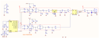
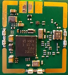
    - The CC1352P and CC1350 are not pin compatible meaning that you can't use the same PCB for both. Also the fact that changing the chip changes the performance is a bit strange. Would you be able to post a screenshot of the RF part of the schematic/ layout to get a better idea? 

    - Could you share how you are measuring RSSI in your FW?

  • Good morning,
    Yes, they are not pin to pin compatible. I meant that those two PCB’s are identical except the part where RF transceiver is fitted. RF shielded section, containing RF transceiver is different but elsewhere the board is identical.

    Schematic

    PCB

    RSSI code 

    RF_cmdRxTest.endTrigger.triggerType = TRIG_REL_START;
    RF_cmdRxTest.endTime = RF_convertMilisecondsToRatTicks(500);
    RF_CmdHandle cmd_handle = RF_postCmd(
        rfHandle,
        (RF_Op*)&RF_cmdRxTest,
        RF_PriorityNormal,
        &RADIO_rxCallbackScan,
        RF_EventRxEntryDone);
    int8_t rssiNow = 0;
    while((rssiNow == RF_GET_RSSI_ERROR_VAL) || (rssiNow == 0)){
        rssiNow = RF_getRssi(rfHandle);
        }
        RF_cancelCmd(rfHandle, cmd_handle, 0);
        RF_pendCmd(rfHandle, cmd_handle, RF_EventRxEntryDone)

  • Additional Information:

    Our programmer narrowed down origin of this issue. Now all boards measure the same RSSI which is about -102dBm.  And I can see RF CW to those levels, when fed from RF generator. The only difference in code is small sleep routine added before actual measurement.

        RF_cmdRxTest.endTrigger.triggerType = TRIG_REL_START;
        RF_cmdRxTest.endTime = RF_convertMilisecondsToRatTicks(500);
        RF_CmdHandle cmd_handle = RF_postCmd(
                rfHandle,
                (RF_Op*)&RF_cmdRxTest,
                RF_PriorityNormal,
                &RADIO_rxCallbackScan,
                RF_EventRxEntryDone);
     
        int8_t rssiNow = 0;
        while((rssiNow == RF_GET_RSSI_ERROR_VAL) || (rssiNow == 0)){
            Task_sleep(1);
            rssiNow = RF_getRssi(rfHandle);
        }
     
        RF_cancelCmd(rfHandle, cmd_handle, 0);
        RF_pendCmd(rfHandle, cmd_handle, RF_EventRxEntryDone);
    

    So it seems like RF_getRssi(rfHandle) returns improper RSSI value which depends from CC1352P  silica die. If we give some idle time with  Task_sleep(1) we get proper RSSI value.

    Now I need to measure actual sensitivity of the system when working with real data packets, real communication. I am no longer confident that we get full sensitivity during communication and it is not tampered my bad noise floor. Unless someone from community sees this situation differently and can explain.

    In general this community has more experience has seen more different scenarios then I, maybe someone can share opinion on this matter? Do I need to worry that during full speed 1Mbps communication I have that inconsistent noise floor as a bottle neck for sensitivity I can achieve? 

  • At first I suspected a HW issue but now I think you have a SW issue. I haven't looked at the timing here but I suspect that you in some cases are reading out RSSI when not in RX. It's possible to set a DIO high when the radio is in RX, I would do that and at the same time set a DIO just before/ after using getRSSI.

    For packets it's easier, the RSSI of the last received packet can be appended to the receive buffer. Have you looked through https://dev.ti.com/tirex/content/simplelink_cc13xx_cc26xx_sdk_6_40_00_13/docs/proprietary-rf/proprietary-rf-users-guide/proprietary-rf-guide/index-cc13xx_cc26xx.html ? 

  • Sorry for being away for few days. First of all, thank you for your time and effort, really appreciate it. Good to know that we always have people to consult with. Here are results of suggested investigation:

    Yellow color is RF Core receive signal, according to used configuration:

    PINCC26XX_setMux(antennaPins, RF_HIGH_PA_PIN, PINCC26XX_MUX_RFC_GPO3);
    PINCC26XX_setMux(antennaPins, RF_SUB1GHZ_PIN, PINCC26XX_MUX_RFC_GPO0);

    Green color is IO pin representing RF_getRssi(rfHandle)

    To my understanding RSSI is measured during receive period. Programmer noted that RSSI measurements are two because function measures until receives valid measurement. Which in our case is still invalid and misleading.

    In any case now we found the cure, small sleep (period of doing nothing) before measurement. I think this means case is closed for us. Just need to do actual receive sensitivity measurement to make sure it is consistent through all the boards.

    Since the RSSI result depends on silica die and RF_getRssi(rfHandle) does not return trustworthy result without external precautions (sleep), maybe errata must be  supplemented?