Other Parts Discussed in Thread: CC1310, CC1101, CC2500, , CC1312R
We have thousands of CC1310 sensors an hundreds of 1310 receivers working and are trying to make a 1352 receiver. We previously tested the R4-1 and R4-2 variants and had no issues. However, we have built a prototype using the CC1352R7-4 and there appears to be vast differences in how the code works. The data stream coming in from the 1310 sensors only worked on some of them, other had certain bit that were corrupted but the corruption was repeatable, the sensors that sent data that was received badly was always received with the same bad data stream. All the sensors work with no issue with a CC1310 based receiver. What we found it that I had been using the CCS project with the processor set to CC1352R7-2 not CC1352R7-4. When I changed that using the .syscfg generating tool, the whole thing went bad. The complier would no longer compile the code. There were differences in the UART file due to the complier no longer recognizing references to the now missing uart.h file. I had to change all that to uart2.h references. Those are all fixed but now the big problem is that none of the RF commands worked. With the CC1352R7-2 code, all my commands were RF_cmdFs based. On the CC1352R7-4, I had to change all the calls to which ever PHY method I chose with is currently the custom 868 mode which needs the commands to be RF_cmdFs_custom868_0 based. I tried several other configuration, changing the base commands each time (which is a total PITA), but nothing works. Another complaint of this is that I had to manually select each PHY command I wanted to use from a checkbox list under the "RF Command Symbols" section.
The closest configuration that almost worked was setting it up as "50 kbps, 25 kHz Deviation, 2-GFSK, 100 kHz RX Bandwidth, Custom PHY Setting, 868 Mhz band" and changing the base commands (RF Command Symbols) to match that. With that, I received my data stream but it was shifted to not include the length byte (first byte) and the first byte of my data. So it looked like the datastream was shifted byte two bytes. However, I still get a PROP_DONE_RXERR as a result of the sniff operation.
With the custom 868 setting, I get no recognizable bytes at all in the received data stream. The wake on radio function works for all variations I tried meaning that I get no jump the sniffing callback function until I send a packet with a sensor, it is just that the data coming in is no good and the result is always PROP_DONE_RXERR.
BTW: I set the following two options so I could see the bad data in the steam:
RF_cmdPropRxSniff_custom868_0.rxConf.bAutoFlushIgnored = 0;
RF_cmdPropRxSniff_custom868_0.rxConf.bAutoFlushCrcErr = 0;
Note that I am currently using the custom868 so that is why the commands have that tacked onto the end of those variables (the CCS makes me do that).
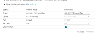
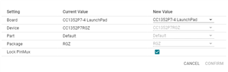
All of this was working with CC1352R7-2 compiled code running on the CC1352R7-2 chip and that code worked a lot better on the R7-4 chip. Changing the CPU variant in the syscfg. tool to
I have tried making small changes to the base frequency (up to 5kHz), RW bandwidth, deviation, and baud rate to test if maybe there was something off in the 48MHz crystal. None of these made any difference.
With the R7-2 and R7-1 variants, TI supplied a working example code for the wake on radio which is what I built my project around. However, the CC1352R7-4 DOES NOT have a working version of the wake on radio example for the 915MHz range, only the 433MHz, which appears to be no different than the code I have been using for the two previous variants of the 1352. That code is also very similar to CC1310 wake on radio code with only the only change being using the .syscfg generating tool instead of the smartRF files. That code will not work for the 915MHz due to the code changes I already mentioned having to use something other than RF_cmdF commands.
Something I should also note is that the CC1310 are using the 4.20 version of the complier and the CC1352 required me to change the complier to the RTOS7 (TI Clang v2.1.0 LTS) because that is what your example program used. In fact, the big problems of it not working on any sensor was when I changed the "Based on RF Design" option in the syscfg tool.
All my working sensors and receivers are using the following RF configuration. All these values were plugged into the appropriate places using the .syscfg generating tool for the CC1352.
//*********************************************************************************
// Generated by SmartRF Studio version 2.23.0 (build#306)
// The applied template is compatible with CC13x0 SDK version 2.10.xx.xx or newer.
// Device: CC1310 Rev. B (2.1).
//
//*********************************************************************************
//*********************************************************************************
// Parameter summary
// RX Address0: 0xAA
// RX Address1: 0xBB
// RX Address Mode: No address check
// Frequency: 921.75 MHz
// Data Format: Serial mode disable
// Deviation: 5.000 kHz
// Packet Length Config: Variable
// Max Packet Length: 255
// Packet Length: 30
// Packet Data: 255
// RX Filter BW: 49 kHz
// Symbol Rate: 5.00031 kBaud
// Sync Word Length: 32 Bits
// TX Power: 14 dBm requires define CCFG_FORCE_VDDR_HH = 1 in ccfg.c, see CC13xx/CC26xx Technical Reference Manual
// Whitening: CC1101/CC2500 compatible