This thread has been locked.

If you have a related question, please click the "Ask a related question" button in the top right corner. The newly created question will be automatically linked to this question.

cc1352p7 protocol for 100 nodes suggestion

Other Parts Discussed in Thread: CC1352R, SYSCONFIG, CC1352P7, LPSTK-CC1352R

Hi

we are able to communicate with our LPSTK and collector in proprietary Rf (Tx)protocols along with the accelerometer. And the current consumption is also fine for us..
since the OAD is concern we would like to go with the Ti-15.4 stack instead of proprietary protocols. Below points are need suggestion from an expert end..

1.15.4 stack is taking 3ma in idle mode and 15ma while transmitting (whereas as proprietary rf takes only few micro amps and 1ma while sending )
2.since our project is cattle health monitor and every time cattles go out of the range and the connection establishing is takes time and sometime manually we have to restart(in proprietary Tx it is broadcasting so that no need to worry about the connection establishing)
3.is it possible to test the 15.4 stack(sensor example from the sdk)in smart RF studio to understand the behaviour?
4.Please suggest us with proprietary rf or Ti15.4 stack for our project considering more than 100 nodes with reconnect (in case of out of range) possibility(auto reconnect is a challenge)

  • Hi Manu, 

    1. The current consumption at TX depends on the amount of time the devices spends in TX and the TX power. For current measurements please ensure the same payload and the TX powers. You maybe interested in the non beacon mode, where the device doesn't need to wake up periodically and switch on RX to get the beacons transmitted by the collector. 

    https://dev.ti.com/tirex/content/simplelink_cc13xx_cc26xx_sdk_6_40_00_13/docs/ti154stack/html/ti154stack/non-beacon-mode.html

    2.  The orphan rejoining should be taken care of by the stack. Once the device goes out of range and comes back into range, the stack automatically starts sending orphan notifications to the coordinator, which should allow the node to rejoin the network.

    Check "Maintaining a Connection for End Nodes" section in the above link.

    3. Smart RF studio is used for RF performance evaluation. The 15.4 stack has the mac layer and can be tested with the collector sensor examples. Try the simple link academy sensor collector project zero found in the following link. 
    The simple link academies: dev.ti.com/.../node

     The stack user guide: https://dev.ti.com/tirex/explore/node?node=A__AHaph7YfvcrVy2cDlmb4sQ__com.ti.SIMPLELINK_CC13XX_CC26XX_SDK__BSEc4rl__LATEST

    4. The 15.4 network does bring advantages like collision avoidance during transmission with LBT/CSMA, network maintenance, security etc. But as you pointed out, this causes some additional overhead.  It is up to you to evaluate if you need these features or not. 

    With the proprietary network, you do get more granularity and control over your TX and RX and the overhead is lower. But you need to make sure that the messages are scheduled correctly so that the receiver is actually in the RX when you transmit from the transmitter. Also any node can receive your message, there is no implicit addressing involved. If you do not have any encryption any one can read these messages. 

    Our suggestion would be to evaluate the TI 15.4 stack with a collector and a few sensors in the different modes and check the performance and see if it is acceptable compared to your proprietary network. 

    Hope this helps. 

    Regards,

     Sid 

  • Thanks a lot siddanth for your valuable suggection..

    we have programmed LPSTK cc1352R as node and CC1352P7-1 as collector..(Ti 15.4 stack)..the current consumption is bit high in the idle condition any suggestion is highly recommended to lower the same..

  • Hi Manu, 

    I assume you are concerned about the node's current consumption. Which mode are you operating the network in. Beacon, Non-Beacon or Frequency Hopping mode?

    Regards,
    Sid

  • Yes siddanth...it is operting in the Non beacon mode

  • Hi Manu, 

    Have you measured the current consumption after the node has joined the network? 

    In the beginning during the network joining, the node needs to be in the receive mode to receive the collector's data. But once, it is joined, it is allowed to go to "sleep mode" where it doesn't have the Rx on always but switches it on only when necessary. 

    Regards,

    Sid

  • Hi Siddanth

    This point need to be exercised, i will check the same and update you with in no time.. 

  • Hi Siddanth 

    it is taking 5mA even after establishing the connection.

  • Hi Manu, 

    This might be from the reporting interval. The sensor transmits data every 3 seconds in the default setting. If you increase the reporting interval and the poliing interval, then the device on an average will sleep more and will be less in TX and Rx , you can find the parameters you need in your network, within the advised limits, which is mentioned in sysconfig. 

    Regards,
    Sid

  • Hi Sid

    we have tried changing all the interval and polling time but no use …may i know in your side what would be the idle current consumption of LPSTK CC1352R with 15.4  sensor stack running ?so that we will have some hope for the workarounds..

  • Hi Manu, 

    I am sorry for the delays. I am off for this week. I shall perform the measurements on Monday and update here. 

    Regards,
    Sid

  • Hi Siddanth...

    hope you are able to get the power consumption in LPSTKCC1352R with 15.4 Stack...there are few more questions which we wanted ask..

    1.can we do OAD with proprietary protocols?

    2.can we use tiny ML in cc1352P7 controller?

    3.Since the cattle data(x,y,z) need to be stored can we use the onboard Flash memory (8mbit)?

  • Hi

    any one else can support on this thread ..its been a long while waiting for the reply...

  • Hi Manu, 

    I apologize for the delay. Unfortunately we are very bandwidth limited at the moment. But I was able to measure the current consumption on a CC1352R Launchpad. which has the same device as the LPSTK board. 

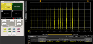
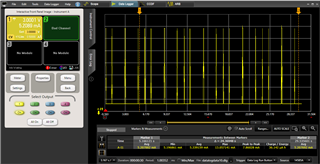
    The current measurement with the default parameters matched yours. 5mA average current. 

    But when I removed the connection to the LED on the board, it did reduce to ~1.5mA. So the LED does take up a lot of the current measured.

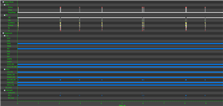
    I used energy trace++ to ensure that the correct states were reached. The CPU seems to enter idle most of the times. 

    Non beacon mode without LED. 

    with LED connection: 

    Regards,

    Sid

  • Hi Manu, 

    1. We have deprecated Easylink, you would have to build your own OAD application if you want to use OAD with proprietary RF. 

    2. TinyML is not something we directly support on our connectivity devices. But we are already a supported device for edge impulse's AI eco system. 

    https://docs.edgeimpulse.com/docs/development-platforms/officially-supported-mcu-targets/ti-launchxl

    3. You can use the external flash. The example nvs external allows you to use this. 

    https://dev.ti.com/tirex/explore/node?node=A__ADgLKV1xFmspgqBKQcgOGA__com.ti.SIMPLELINK_CC13XX_CC26XX_SDK__BSEc4rl__LATEST

    Regards,

    Sid

  • Hi Sid

    Thanks for the reply …3mA for idle power consumption is a lot …also how  "ti "can offer battery life of 10 years with the 15.4 stack (asynchronous mode) ?..(two AA battery would be having 2500mAh,will run only less than 34 days )..

    please refer the document from ti(Using the SimpleLinkTm Sub-1 GHz 15.4-Stack: Choosing Between Synchronous / Asynchronous Mode)

    www.ti.com/.../swra614.pdf

    ref-Application Report SWRA614–October 2018

    Page number- 3

  • Let me check with RnD regarding the configuration settings that are needed to generate this. It talks about 10 minute and 20 minute polling and reporting interval. There is also a possibility that they power cycle the sensors to achieve this lifetime. There is a battery life calculator available as a part of the collateral package of 15.4 stack. I will check how these lifetimes are achieved. 

    dev.ti.com/.../TI-15.4-STACK-CALC.html

  • I suggest to not use the LPSTK-CC1352R for sensor node if you want to achieve low power consumption during operation. The LPSTK-CC1352R sensor node example program has open UART and several I2C sensors which will add to current consumption. To completely cut off current consumption of I2C sensors you would need to cut off power going to it one way is to use MOSFET switch.

    I suggest you use the CC1352R1 Launchpad as sensor node. This way there are more flexible options to reduce current consumption of the device.

    Also, for 10 year battery check out this reference design which uses nano power system timer.

    https://www.ti.com/tool/TIDA-00484

    For measuring current consumption, see below. You can not use digital multi meter to measure the current consumption. From the document need to use DC power analyzer.

    https://www.ti.com/lit/an/swra478d/swra478d.pdf

    -kel

  • Thank You for your reply..

    we are able to get very low power consumption in the same LPSTK with proprietary rf with  accelerometer enabled..

    (idle current is few micro amps and 15mA while transmision)

    only the challenge is with the  15.4 stack which will be having OAD ready and data encryption …please  suggest ..

    since our project will be having more than 100 nodes and 3.6mAh battery for each node our prime goals are

    1.battery life(2 years )

    2. range(~1km)..

    3.OAD

    4.tiny ML(edge impulse)

  • OAD you can do already through BLE with the DMM example program. Battery life and range you need to test. I can not comment regarding encryption as I have not tried it. Anyway, I think your objectives are doable.

    -kel

  • hi 

    only the challenge we are facing in the 15.4 is the power consumption ..how can i reduce the same. We have another board cc1352p7-1 ..still we are not able to reduce the consumption...

  • Hi,

    You need to analyze the current consumption over time. Details already mentioned below. 

    https://www.ti.com/lit/an/swra478d/swra478d.pdf

    You can increase the transmission interval for example every 30 minutes. Also when you are done reading the sensor you can cut off power going to it using example mosfet switch circuitry. There are other circuitry to do this. There is also a circuitry to shut off power to entire system reference design below. Open UART and LEDs contribute to current consumption.

    https://www.ti.com/tool/TIDA-00484

    For your central device the receiving side much better if it is constantly powered or have a big rechargeable battery. Maybe solar power plus rechargeable batteries.

    -kel