Other Parts Discussed in Thread: , CC1200
Hello expertes.
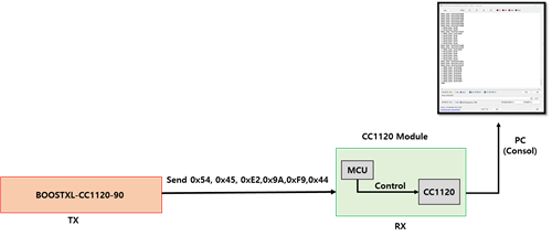
I am a person who is experimenting with the CC1120 in the environment shown in the picture below.

The CC1120 module acts as a RX and is composed of an mcu and a CC1120 chip, the CC1120 chip is controlled by the MCU.
The CC1120 module is manufactured, not a commercial product.
BOOSTXL-CC1120-90 is used as TX and is a commercial product of TI.
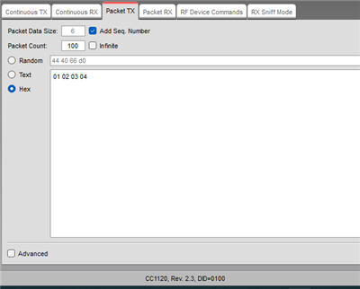
BOOSTXL-CC1120-90 interlocks with SMART RF and can transmit packets with the set Carrier Frequency through Packet TX of SMART RF in PC.
However, I am not receiving anything from the CC1120 Module.
I thought that the received data would be stored in the RX FIFO (0x3F) and the received data could be read by reading the 0x3F register.
However, as a result of reading NUM_RXBYTES that can read number of bytes in the RX FIFO, 0x00 was read.
Even when reading the RX FIFO itself, 0x00 was read.
I used two BOOSTXL-CC1120-90 and set one to TX and the other to RX to conduct a RF test.
At that time, it was confirmed that packets were transmitted and received normally.
The register value of BOOSTXL-CC1120-90 used for RX was extracted by using SAMRT RF and applied to CC1120 module as it is.
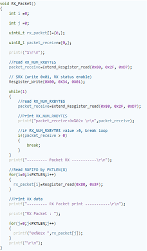
In my opinion, there seems to be a problem with the way srx is strobe or rx fifo is handled after inputting the register value.
The picture below is the code that writes the value to the register, executes manual calibration, and then executes it.
The code tried to run in the form of continuously reading NUM_RXBYTES and reading RXFIFO when the value became greater than 0.
I'd really appreciate any suggestions on what to fix or fix in the code above.
Thank you so much for reading long post.
- by KIM -


