This thread has been locked.

If you have a related question, please click the "Ask a related question" button in the top right corner. The newly created question will be automatically linked to this question.

LP-CC1352P7: LP-CC1352P7-1 RX Sensitivity Test

Part Number: LP-CC1352P7
Other Parts Discussed in Thread: CC2531EMK, CC1352P7, CC1312R, CC1312R7

Hello,

I would like to test the RX sensitivity of this Wi-SUN device for the 902-928 MHz band. Could you please guide me how to perform this RF test? The test would be performed for over-the-air and conducted. 

FYI, we plan to order the LP-CC1352P7-1 and AM64 Starter Kit EVM. 

Thanks

  • Hi,

    For conducted testing: SWRA370 (Basic RF Testing of CCxxxx Devices): https://www.ti.com/lit/swra370

    For radiated testing: SWRA479 (Achieving Optimum Radio Range): https://www.ti.com/lit/swra479

    Regards,

    Zack

  • Hi,

    is the CC2531EMK the correct eval module for LP-CC1352P7-1 eval board? or the AM64 Starter Kit EVM is the right one? Thanks.

  • The LP-CC1352P7-1 is the evaluation board for the CC1352P7 (with RF paths optimised for 868/915 MHz +14 dBm RX/TX, 2.4 GHz +5 dBm RX/TX, and the HPA for 868/915 MHz +20 dBm TX) - you can order them from here: https://www.ti.com/tool/LP-CC1352P7#order-start-development

    It is a SoC, not a transceiver, so it can be used for development by itself.

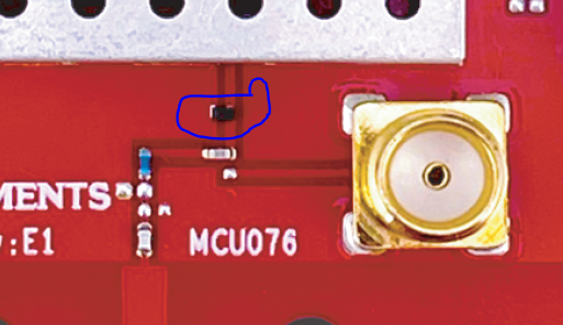
  • Hi, I used the external antenna for evaluation. I removed the capacitor and use 0 ohm resistor to connect to the connector. Do I need to remove the little black component, as shown in the picture? is it part of the matching network for the PCB antenna? Thanks

  • Hi,

    It is an ESD protection diode and is not part of the RF matching; you can leave it mounted.

    The capacitor is a DC block so you need to switch the paths using that capacitor, not replace it with a 0R resistor. The RF switch can cause sub-optimal performance if this DC block is not present so you will need to re-mount it.

    Regards,

    Zack

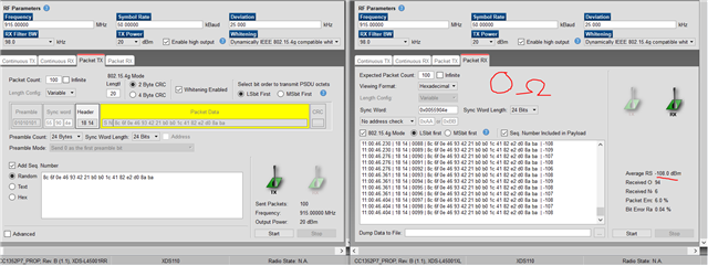
  • Thanks Zack. When I switched back to capacitor (with 130 dB attenuation), the PER improve (always <1%), but the RSSI getting worse (around -98dBm), compare to using 0 ohm resistor (with 95 dB attenuation). This is for conductive test. Do you have any idea why this happened?

    In addition, I guess I may need to use this DC block cap for my design, right? If so, what is the value of this cap since the datasheet doesn't show any info about it? Thanks


  • Please can you double-check your soldering? It is the most likely cause in this case.

    The Sensitivity should be in the range you are seeing with the 0R resistor with the capacitor mounted (from the datasheet, at least -107 dBm for 50 kbps, ±25 kHz deviation, 2-GFSK, 98 kHz RX Bandwidth, 918.2 MHz, 10% PER, 250 byte payload) The LP-CC1352P7-1 has had extensive conducted testing for this PHY during Validation so we are confident this is not an issue with the design; please include this DC blocking capacitor in your design.

    Here are the design files for the LP-CC1352P7-1 (SWRC372): https://www.ti.com/lit/zip/swrc372

    The capacitor value is 47 pF (C16 in the screenshot of the schematic in my previous post) - you can find the exact part number in the BOM list in the design files.

    Are you only operating at Sub-1 GHz frequencies and do you need the +20 dBm output? If not, you could use the CC1312R for this application. 

    For future evaluation I recommend testing the board in its unmodified state first (i.e. using the PCB antenna) just to check that you get the expected performance out-of-the-box as it can help with these kinds of issues later on.

    Regards,

    Zack

  • Hi Zack,

    I have checked the solder and they are fine. I have 3 different boards and they have similar results. Not sure why. With the 0R resistor on 3 boards, I got the RSSI approx -108 dBm which is closed to the datasheet, but not with the DC block cap. I thought the result should be similar for either DC block cap or 0R resistor. Any advice?

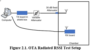
    Because we use external antenna in our application, I decided to switch to the connector. I used cables for the conducted test, and external antenna for OTA radiated testing inside the chamber. So that, it would be closed to the real application.

    Yes, we actually need 30dBm Pout at the antenna in our application, so that, I test with 20 dBm max of this board. Our current application is 902 - 928 MHz, but plan to use 2.4 GHz band in the future.

    Thanks

  • Are the replacement capacitors the same series (or at least type) as in the LP-CC1352P7-1 BOM? The performance should be similar to the datasheet with the capacitor mounted.

    Are the measurements you shared conducted?

  • Hi Zack, yes, they are the original capacitors of the boards since I didn't throw them away. 

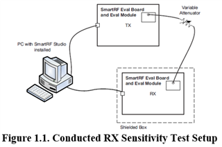
    Yes, the above measurements are conducted using cable and variable attenuator to connect 2 boards together. I increased the variable attenuator from 0 dB to 140 dB. With the DC block cap, I still cannot get the PER close to 10% (which is used in our application) in order to observe the RSSI. That is why I feel something not right. With 0R resistor, I was able to get the expected results with attenuator about 99dB.

    I wonder if the datasheet show conducted or OTA radiated test results?

    Thanks for your help and time.

  • The datasheet shows conducted measurements with the capacitor mounted. I also double-checked measurements on this board myself just now (conducted) and they match the datasheet performance, so I agree that this is not the expected behaviour.

    A couple of further steps to try: 

    • Does this difference occur when not using the +20 dBm output for TX (i.e. the +14 dBm output)?
    • If you replac(ed) the 0R back on one of the boards does the Sensivity return to the expected range?
    • Can you place one of the boards in a shielded box as recommended in SWRA370?
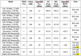
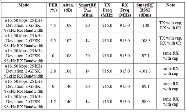
  • Hi Zack, the TX board is always placed in the shield box for conducted test. Please see below snip as the data that I collected with various TX power for the RX board with cap and RX board with 0R.

    For RX board with cap, 14dBm Pout gave reasonable results. However, increase the Pout, RSSI decrease. To my knowledge, increase Pout with same attenuation, PER should decrease and RSSI should stay same or increase.

    I could be wrong, but with 0R resistor, the values look reasonable. With 20 dBm Pout and 108 dB attenuation, PER is 4.5%, RSSI is -108dBm. Using same 108dB attenuation and 14dBm Pout, both PER and RSSI are bad, as shown in the snip. Decrease the attenuation to 102 dB, PER and RSSI are reasonable. This sounds more right to me. FYI, I ran multiple TX packet to observe before recorded the data.

  • Could you also take a picture of your board using the DC block? 

    Also: As the schematic shows the signal goes into a switch that require a DC block:

    Not sure: Do you use the same type board for both RX and TX with the same modification? 

    On the side:

    "Yes, we actually need 30dBm Pout at the antenna in our application, so that, I test with 20 dBm max of this board. Our current application is 902 - 928 MHz, but plan to use 2.4 GHz band in the future."

    What do you base the output requirements on? The range is not the same on 2.4 GHz, even with the same output power, and the max allowed power on 2.4 GHz is lower than 30 dBm. 

  • Hi, I used the same 3 board LP-CC1352P7-1. Right now, I have the TX board with DC block cap, 1 RX board with cap, 1 RX board with 0R resistor.

    For now, we just evaluate the 915 MHz band. We plan to use PA to achieve the 30 dBm at the antenna since 30dBm is required for our application.

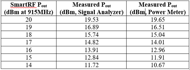
    Also, I measured the TX Pout using signal analyzer (cable connects the TX board to signal analyzer), the measured Pout is actually less than the TX Pout in SmartRF. Only the 20 dBm (SmartRF) give close measured value of 19.37 dBm. That is the reason why I tested with 20dBm set in SmartRF. The measured RX Pin with 0dB attenuation are expected due to the losses of variable attenuator. Thanks

  • Please move one of the boards with the capacitor mounted back to a 0R (and remeasure), then remount the capacitor (and remeasure) - this will help clarify if it is a soldering issue.

  • Good morning, the same RX was mounted back with DC block cap and collected data with 108 dB and 140 dB attenuation and Pout of 14dBm and 20dBm. The PER don't change much with same Pout, while the RSSI decreased a bit (~3dBm) when increased the attenuation from 108dB to 140dB. However, RSSI is not closed to -108dBm, compare to datasheet and RX mounted with 0R resistor. I expected both PER and RSSI getting worse when the attenuation is significantly increased, but it doesn't seem like that. Any thoughts? Thanks.

  • I have contacted your FAE - this is easier to debug with boards that we know for certain are performing as expected.

    Therefore, I will modify 3 LP-CC1352P7-1 boards to use the SMA path, measure the RX Sensitivity to ensure it matches the datasheet performance, then send them directly.

    This will help rule out the boards themselves as the root cause.

    Regards,

    Zack

  • Thanks for your assistance. Also, could you please measure the Pout at the TX board to verify if the measured Pout is similar to TX Power at SmartRF. Based on my measurements as shown below table, there are about 2.5dBm loss when set TX Power from 14 to 19dBm at SmartRF. I also confirm the measurement using both Signal Analyzer and Power Meter. I directly connected the TX board into the Signal Analyzer and Power Meter using RF cable. Many thanks.

  • I will do that as well and let you know once the boards have been sent.

    Regards,

    Zack

  • I have measured 3 LP-CC1352P7-1 LaunchPads, both TX and RX conducted, and all 3 have the expected RX Sensitivity. I will aim to send them either tomorrow or early next week.

    Please accept my friend request and I will send you the results which you can use as a reference when you receive the 3 boards.

  • Hello Tuan,

    I will be visiting your location next week and per the thread with Zack above, we just want to make sure you are making the progress you intend right now.

    Can you let us know where this stands, perhaps prior to our visit next week, so that we can prepare beforehand accordingly?

    Thank you all,
    Chris

  • Hi Chris,

    I have collected some data from the 3 boards that Zack sent.

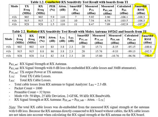
    For the conducted testing (section 6.1 in swra370), the RSSI values (recorded from SmartRF) look reasonable, comparing to -109dBm that Zack measured (he used section 7.1 in swra370).

    For the radiated testing, there are 4 to 6 dBm difference, comparing to conducted test with the corresponding frequencies. I wonder why there are that much difference. Not sure if the RX antenna is affected by the noise of the board or what happens. I am still thinking about the possible causes.

    FYI, the comparison between conducted and radiated RSSI is to determine how the noise floor impacts the RX sensitivity and what is the expected RSSI in practical. Then, we can try to improve the design in order to achieve the radiated level close to the conducted level.

    Thanks

  • Hi Tuan,

    Glad to hear that the conducted performance is now in line with the expected values.

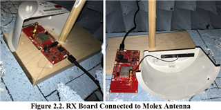
    Could you share details of how you are connecting the Molex 105262 antenna to the EM board? The information I can find about it indicates that it does not use an SMA connector (the datasheet states a U.FL connector).

    Regards,

    Zack

  • Hi Zack,

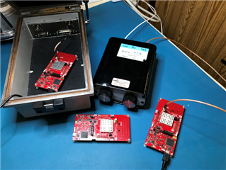
    Please see below pictures for the flex antenna and mounting location. I use the SMA-to-U.FL adapter to connect the antenna to the board. In our application, the board will be much closer to the antenna, which mounted on the housing (less than 1/2 inch from the board). As a result, I think the sensitivity of the CC1352P7 in our application will be little worse than the data that I am testing right now. Thanks

  • Are you able to measure the S11 of the antenna both in free space and then attached to the casing? It is possible that the casing is shifting the antenna's resonance (i.e. dutuning the antenna) so it is important to confirm this. Section 6.2.3 of SWRA161 (AN058 – Antenna Selection Guide): https://www.ti.com/lit/swra161 gives more information about this (Figure 16 demonstrates the potential effect of plastic casing with real-world measurements).

    You could also try measuring the radiated performance with the antenna not attached to the casing (if possible).

    Additionally, have you double-checked that you are following the assembly guidelines outlined in the manufacturer's documentation? From what I can find, this is detailed in AS-1052620001 on https://www.molex.com/en-us/products/part-detail/1052620001 - p12 and p13 indicate that the positioning of the cable is important for performance.

    Regards,

    Zack

  • Hi Zack,

    Yes, I did measure the S11 of the Molex antenna in both free space and inside the meter with the same mounting location on the housing. The S11 is very good, VSWR of 1.9:1 max across the band (902 - 928MHz). We are currently using this antenna in our product and plan to use it for the next generation.

    I agree the position of cable also impact the performance. I have checked and this antenna's VSWR is very stable.

    May I ask another question regarding the CC1312R7 (sub-GHz only)? We are thinking to consider CC1312R7, instead of CC1352P7 because we don't use 2.4GHz band in our applications. How comparable between CC1312R7 and CC1352P7? What is the longevity of CC1312R7 since it was released in 2018? I think they would be the questions I would ask Chris during the meeting this week.

    Thanks and Have a great day.

  • Thanks for the feedback.

    It is probably easier to discuss these questions further ect. in the call as there will be Applications support present this week (it's always good to get a heads-up beforehand so we can start confirming the answers for you).

    However, some points I can address now:

    We are thinking to consider CC1312R7, instead of CC1352P7 because we don't use 2.4GHz band in our applications. How comparable between CC1312R7 and CC1352P7?

    • The Sub-1 GHz radio performance of the CC1312R7 is the same as the CC1352P7. If you are not using the 2.4 GHz band for your applications then this is definitely the kind of use-case that the CC1312R7 is suitable for.
    • An overview of our current Sub-1 GHz products are found here: https://www.ti.com/wireless-connectivity/sub-1-ghz/overview.html and TI can give more information about upcoming Sub-1 GHz products in the call if required.
    • However, if you need +20 dBm output power then the CC1352P7 would be required as the CC1312R7 has a maximum output power of +14 dBm unless a front-end module is used.

    What is the longevity of CC1312R7 since it was released in 2018?

    • This is best discussed in the call as I don't have the specifics and probably won't until the day of the call. I would also assume that this depends on what is meant be longevity in your case. The short answer would be that it will be supported for the foreseable future, though.

    Regards,

    Zack