This thread has been locked.

If you have a related question, please click the "Ask a related question" button in the top right corner. The newly created question will be automatically linked to this question.

CC1352P: CC1352P: Custom board rf switch pin configuration

Part Number: CC1352P

We developed a custom board based on CC1352P.

Facing an issue in finding correct rf switch pin configuration for PA path.

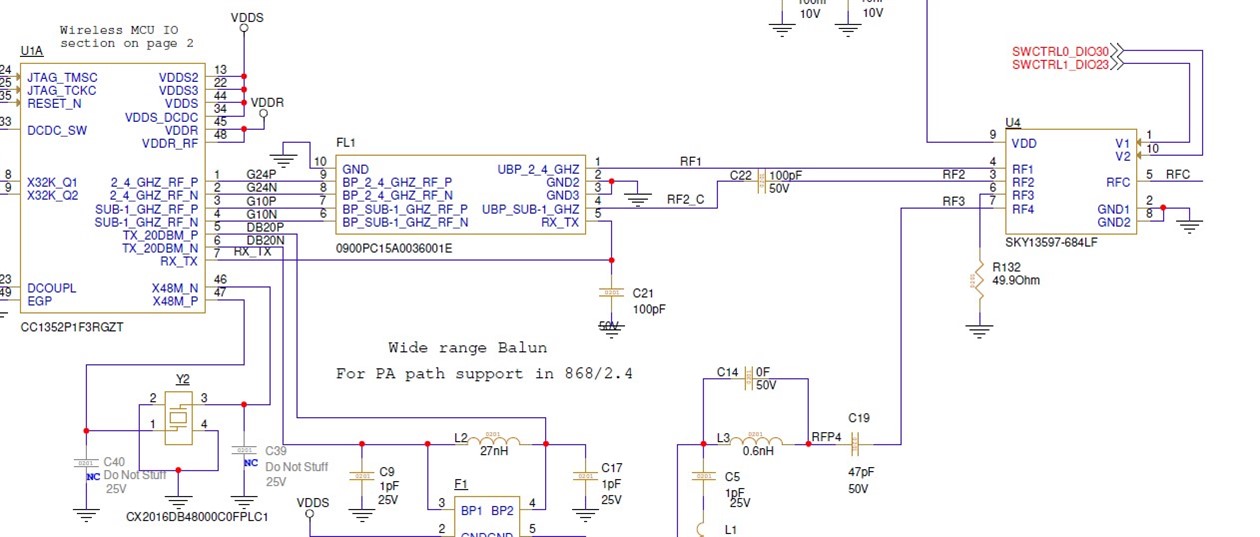
here is RF path schematics:
SKY13597 logic truth table:

According to RF path:

On Sub1Ghz PA  Tx mode, the RF switch is configured to RF4 --> V1 (DIO23) = L , V2 ( DIO30) = L

On sub1Gz Rx mode , the rf switch is configured to RF2 -> V1(DIO23) =H  , V2( DIO30) = H

Unable to find RF Core Data Signals for MUX configuration using PA and LNA for both IO :

 GPIO_setMux(CONFIG_RF_ANTENNA_DIO23, IOC_PORT_RFC_GPO0);  --> Rx = H , Tx = L  : OK

However, CONFIG_RF_ANTENNA_DIO30 needs a similar mux configuration to set it to HIGH on Rx mode and to LOW on Tx mode.

Any idea forDIO30  mux configuration which can be used?

  • Hi Amit,

    for sub-1GHz operation you can mux both DIO23 and DIO30 to LNA enable. When you set the device in receive, RF2 (Sub-1GHz rx) would be routed to RFC (VC1 and VC2 high) and when the device is in transmit, RF4 (Sub-1GHz 20 dBm Tx) would be routed to RFC (VC1 and VC2 Low).

    When you setup the radio for 2.4 GHz you can fix the signals to VC1 high and VC2 Low.

    You can modify the IF statements that configure the pins in the rfDriverCallbackAntennaSwitching() function from ti_drivers_config.c similar to the below code:

    if (sub1GHz) {
        /* Sub-1 GHz */
        if (paType == RF_TxPowerTable_HighPA) {
            GPIO_setMux(GPIO_VC1, IOC_PORT_RFC_GPO0);
            GPIO_setMux(GPIO_VC2, IOC_PORT_RFC_GPO0);
        } else {
            // LNA enable routed to both VC1 and VC2
            GPIO_write(GPIO_VC1, 1);
            GPIO_write(GPIO_VC2, 1);
        }
    } else {
        /* RF core active --> 2.4 GHz */
        GPIO_write(GPIO_VC1, 1);
        GPIO_write(GPIO_VC2, 0);
    }

  • Thanks for the quick reply.

    Actually already tried to mux both DIO23 and DIO30 to LNA enable.

    The problem is that in case of PA Tx , The received signal rssi on launchpad was very low, -90dBm.

    When PA is disabled, ( <=13dBm) , the received rssi on launchpad is ok, around -30dBm.

    It seems mux both DIO23 and DIO30 to LNA enable is not working correctly. 

  • Hi Amit,

    If I understood correctly with DIO23 and DIO30 both muxed to LNA enable when your custom boards transmits using the 20 dBm PA the RSSI reported by a launchpad is -90 dBm and when you use the Sub-1GHz for Tx, the RSSI is around - 30 dBm?

    Have you measured V1 and V2 with an oscilloscope or logic analyzer to verify that they are turning on and off correctly?

  • Hi,

    Issue was found:

    It seems the filter balun on the PA RF path was assembled flipped ( Wrong way). After fixing the assembly, It works as expected.

    Appreciate the support!