- Ask a related questionWhat is a related question?A related question is a question created from another question. When the related question is created, it will be automatically linked to the original question.
Original question:

Hi
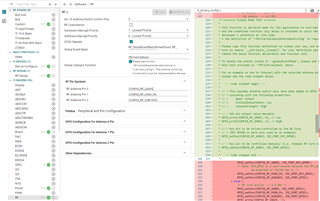
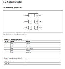
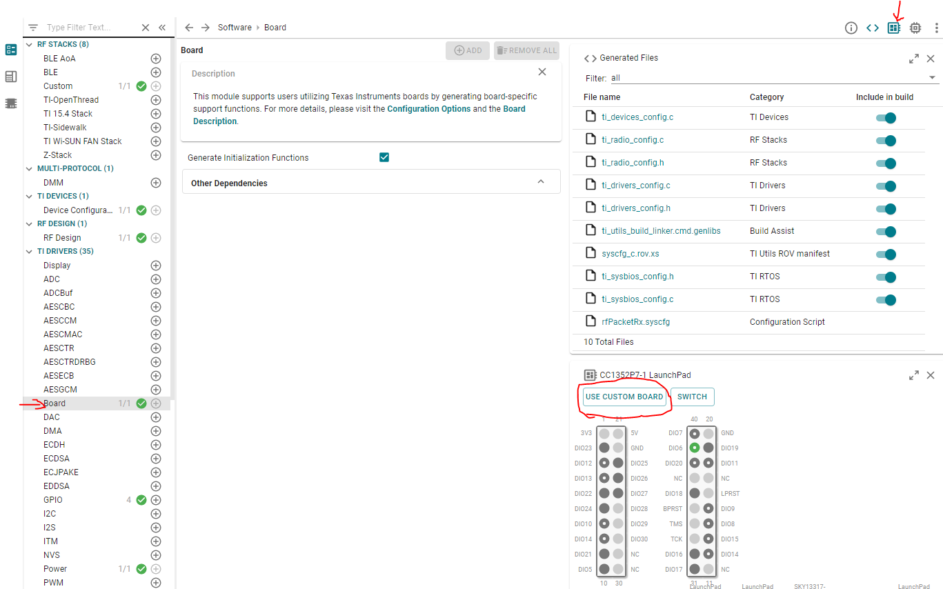
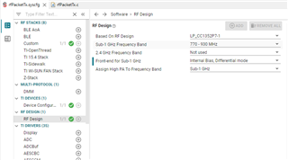
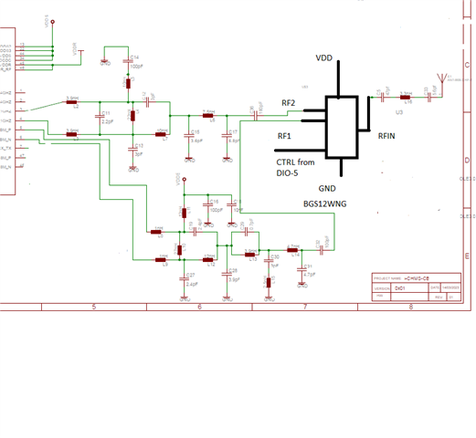
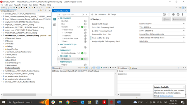
We are using custom module based on CC1352P7 which is only having sub1 Ghz(2.4Ghz is not used ) there by using only an SPDT rf switch BGS12WN6 for switching PA ..
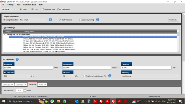
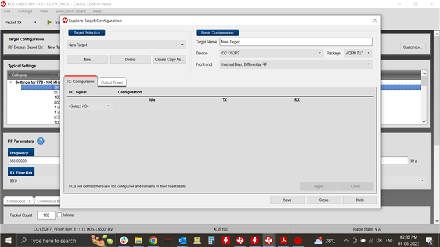
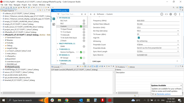
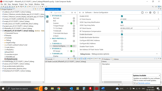
we are able to transmit and receive the data through RF studio with some changes in the IO configuration (DIO 5 enabled with Tx High and RX LOW)...but with the SDK example(Basic TX )which is not working (same is working with the launchpad)..
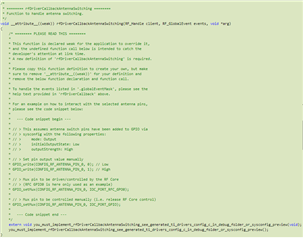
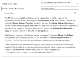
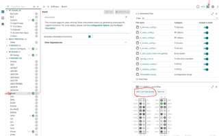
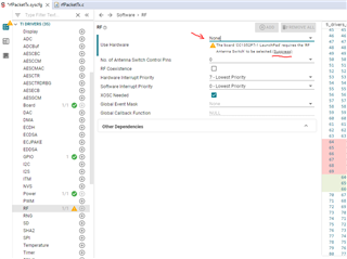
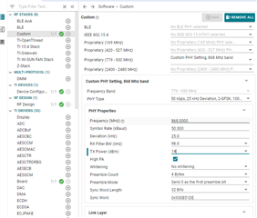
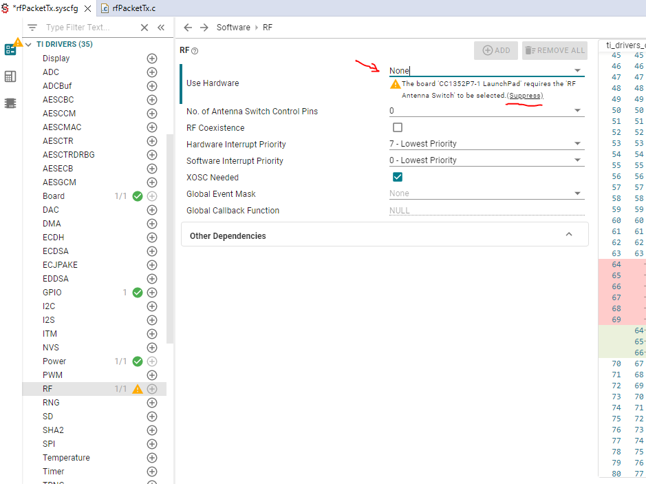
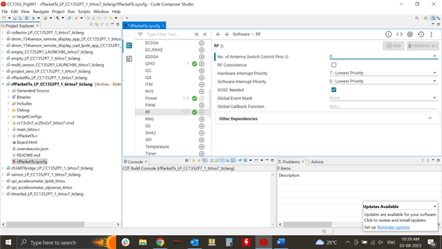
we have tried to change the SKY switch in the sysconfig but end up with some error in the rfDriverCallbackAntennaSwitching section ...please suggest ...