Other Parts Discussed in Thread: , , CC1310, CC1352R
Dear Sir or Madam
We've come across an issue that requires your input.
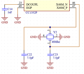
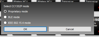
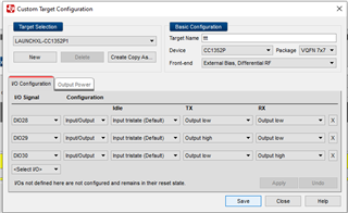
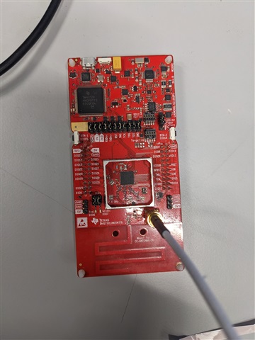
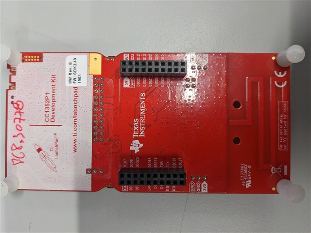
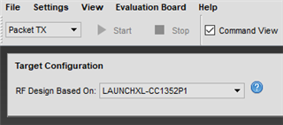
Our devices are based on the CC1352P7 and CC1352P chipsets (5 different products).
The SubG capabilities of the CC chips are used for short-range communication between our devices.
We use a proprietary modulation:
1. GFSK step: 70kbps
2. Bit rate: 50Kbps
3. RXBW: 195.9kHz (enhanced setting is 86)
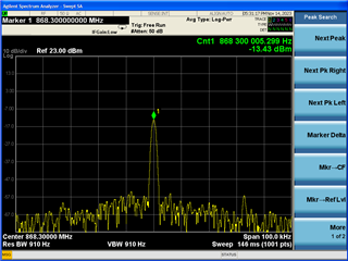
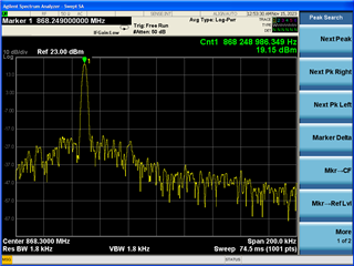
4. Central frequency: 868.3Mhz
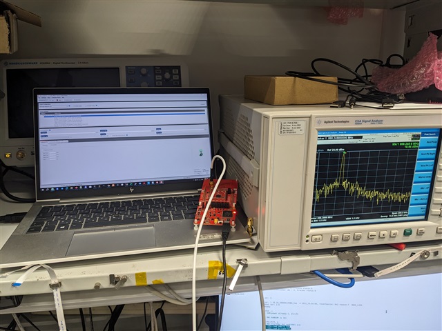
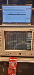
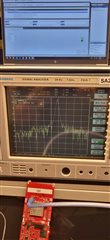
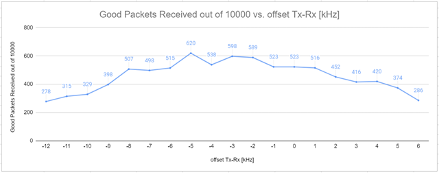
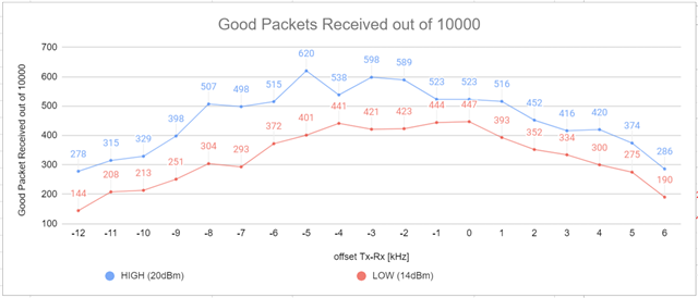
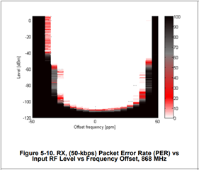
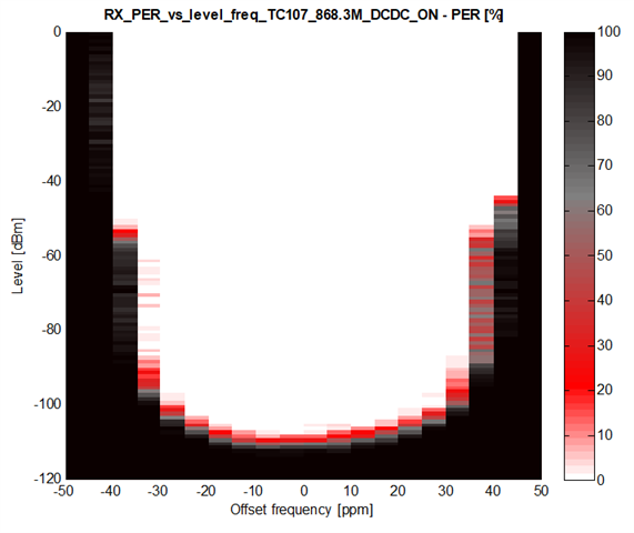
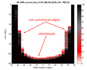
We ran a series of tests to verify the sensitivity of the SubG modem under these conditions.
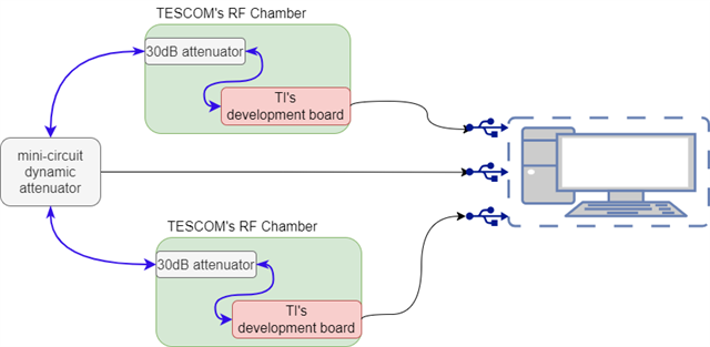
It is important to note that the tests were conducted in a conducted way (not radiated).
To our surprise, we saw that the sensitivity is optimized when the central frequency of the transmitter and the receiver
are not aligned:
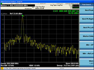
1. When the frequencies are aligned we were able to reach a maximum sensitivity of -105dBm
2. When the frequencies were ~4KHz apart (FTx - FRx ~= 4k) we were able to reach a maximum sensitivity of -107dBm
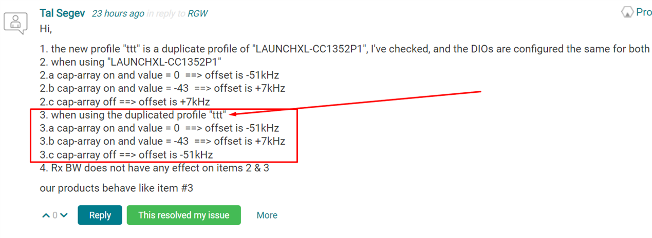
Please note this phenomenon occurs on all five products.
We don't know what causes this phenomenon and would like your assistance in investigating the issue.
Regards,
Tal