This thread has been locked.
If you have a related question, please click the "Ask a related question" button in the top right corner. The newly created question will be automatically linked to this question.
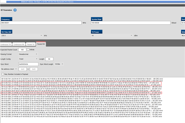
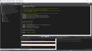
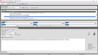
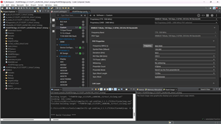
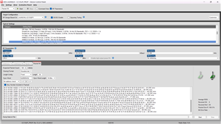
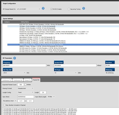
via smart rf studio application , i m able to get WMBUS data in T mode or C mode , but , in app example or composer i m unable to find the WMBUS program , how i can get it or , from where i can download it ?
The Wireless M-bus protocol software for CC13x2 can be downloaded from here:
WMBUS Application software & framework | TI.com
Siri
dose it supports this launchpad devices ,
cc1352P1
cc1352P7-1
becouse i have tryed with the hex file persent in the
folder -> wmbus_cc13x2_rtos_1_0_1\examples\rtos\CC1352R1_LAUNCHXL\wmbus\hexfiles
?
We do not offer wmbus support for the CC13x2x7 devices.
The hex files are for CC1352R, but you should be able to re-compile it for CC1312R as well.
There are no support for the CC1352P in the stack.
BR
Siri
ok siri ,
can you provide me sample source code of WMBUS , working with any board.
or how i can use the WMBUS of cc1352P1, cc1352P7-1 chipset ?
No, I can not.
As I have already told you, we (TI) do not only have a wmbus stack for CC13x0, and CC1312R or CC1352R.
Why do you need to use a P-device?
Siri
in smart rf studio i m able to get data from WMBUS using this two devices cc1352P1, cc1352P7-1 , that's why i m asking
i have only P-device with me now , that's why i want to use P-device .
Even if the device itself supports wmbus from an RF point of view, it does not mean that we have a stack for it.
If there are no need for you to use a P device due to output power requirements, I would strongly recommend that you get a CC1352 or CC1312 LP instead.
You will be able to download the current CC1352R stack to a CC1352P device, but RF performance will be bad since there are no implementation of controlling the switch present on the P Launchpad.
You can off course also try to implement the switching in the stack yourself, based on our prop code examples for the CC1352P devices.
Please note the the stack (CC13x2) will NOT run on a CC1352P7 device, only CC1352P.
Siri
i m trying to change frequency from the given rfUARTBridge.syscfg, but it is giving me an error , there is no error in any file i am only changing the frequency.
can you help me in this.
Please provide info regarding what SDK version you are using and the CCS version.
I used the latest SDK (7.10) and CCS 12.2 and did not experience any problems:
From your screenshot it seems like you have change other things and just the frequency, as the default output power for this example on the CC1352P1 is 20 dBm and not 14, as your screenshot is showing.
Siri
CCS version - 12.3.0
SDK - 7.10.01
in dropdown it is showing only -20 to 14 dBm option , that's way i m selecting WMBUS T mode , it is automatically selecting the dBm.
Sorry, but I do not understand what you are trying to do, or why.
By default, the CC1352P1 UartBridge example is configured as follows:
If you want run the example with wmbus T mode settings instead (why???) you can change it as follows:
It is not possible to set the output power higher than 14 dBm when selecting wmbus, T-mode, due to regulatory requirements (ETSI).
Siri
I have done this but i am still unable to receive WMBUS Meters Data , also i have tested with Two CC1352P devices but it is not receiving each others Data in WMBUS T - Mode.
how i can solve this ?
Again, please be clear on what you are trying to do. Are you testing the wmbus stack or an example in the SDK using wmbus settings?
You cannot run the examples in the stack and receive anything with SmartRF Studio or the proprietary RF examples (even if Studio or the examples are using wmbus PHY), as the packet format used by the stack is not supported in Studio or in our examples.
Please tell me exactly what you are trying to do here.
i just want to receive Wm-BUS data using CC1352P1 or CC1352P7-1.
i m trying to change frequency in a sample program or rfUARTBridge to get Wm-Bus data.
Many of our devices support the different wmbus PHYs (RF settings, like data rate, frequency, modulation format, deviation etc.) and for some of our devices we have special patches that also takes care of for example the 3-out-of-6 encoding/decoding used in T-mode, so that you do not have to do this manually in SW after data is received on the air.
Using SmartRF Studio, you can select the different wmbus PHYs and do packet error rate testing to check our RF performance etc. but the packet sent are not “real” wmbus packet. That means that they do not send packets with a packet format (length fields, crc etc.) compliant with the wmbus packet format (the packet format is different for the different modes also).
What you can do with SmartRF Studio is to for example select T mode settings (PHY) and set the device in RX mode using fixed packet length mode.
If you for example run the meter code from our CC13x2 stack on one device (I used the CC1312R1 and the Apl_CC1352_Meter_T2_C2 example) and then use SmartRF Studio on another device, you will be able to receive packets from the Meter:
Since Studio uses fixed packet length mode and the default CRC of the CC13x2 (and not the wmbus CRC) all packets are of the same length and all of them are showing CRC error.
However, you can distinguish the packets sent from the meter from other packets/noise by looking at the RSSI (much stronger from the packets sent from the “meter” demo application on my desk.
However, Studio will not decode the wmbus packets for you and not even find the correct lengt and CRC, so not sure how useful this is.
This test should be possible to do to listen to other meters as well, as long as know which mode the meters are using.
If you import the settings in one of our code examples (you can use T-mode settings in both rfPacketRx and rfPacketTx example), you can set up a link between the two devices running these two examples, but the rfPacketRX example will not receive any packets from the meter application, since the rfPacketRX example is set up to do packet filtering based on length, and also to discard all packets with CRC errors (which will be all packets from the meter since it uses the wmbus CRC).
The wmbus stack from Stackforce that are available from Ti.com are using the wmbus PHYs but are also implementing the protocols for Wireless M-Bus.
There is a collector example that you can try, but this example installs a (preconfigured) WMBUS meter device into the meter list with the start attributes of the device. After initialization, the collector is ready to receive WMBUS telegrams from the meter devices which are in its meterl ist. This means that it can received messages from a meter device running our meter demo code (not any meter).
We do in other words not provide any sniffer SW for wmbus.
Siri
same thing i want to do but without smart rf studio , i want to see Received WMBUS data on COM Test Serial Monitor. , Wireless M-Bus data is sent by real meter that i want to receive.
can you give me details of Wireless M-Bus PHYs (RF settings, like data rate, frequency, modulation format, deviation etc.) which supports CC1352P1 LAUNCHXL & CC1352P7-1 development kit .
i m also using code exported from smart rf studio but it is giving me error in *import* in a New project .
in rfUARTBridge example project, i m also unable to edit the frequency , Symbol Rate, Deviation which is little bit deferent then the smart rf studio .
i m attaching the SS for it , just to compare.
or in smart rf studio i m also not able to edit frequency , Symbol Rate, Deviation
topic | smart rf studio | CCS Default Values.
frequency | 868.95001 | 868.9500
Symbol Rate | 100.00038 | 100.000
Deviation | 50.000 | 50.0
it can cause any problem ?
The details of the wmbus is given in smartrf studio, by selecting the phy there.
When you have selected for example T-Mode settings in Studio (or using sysConfig, you should NOT change anything, as data rate, frequency, deviation etc. is then set to be compliant with the given PHY).
Also, use the rfPacketRX example, and not the rfUartBridge example as a starting point (you are not trying to make a Uart bridge).
If you use the rfPacketRX example and then replace the sysConfig file and the rfPacketRx.c file with the files attached, you will have a simple RX example receiving fixed 64 bytes of T-Mode packets and printing them on the UART.
/* * Copyright (c) 2019, Texas Instruments Incorporated * All rights reserved. * * Redistribution and use in source and binary forms, with or without * modification, are permitted provided that the following conditions * are met: * * * Redistributions of source code must retain the above copyright * notice, this list of conditions and the following disclaimer. * * * Redistributions in binary form must reproduce the above copyright * notice, this list of conditions and the following disclaimer in the * documentation and/or other materials provided with the distribution. * * * Neither the name of Texas Instruments Incorporated nor the names of * its contributors may be used to endorse or promote products derived * from this software without specific prior written permission. * * THIS SOFTWARE IS PROVIDED BY THE COPYRIGHT HOLDERS AND CONTRIBUTORS "AS IS" * AND ANY EXPRESS OR IMPLIED WARRANTIES, INCLUDING, BUT NOT LIMITED TO, * THE IMPLIED WARRANTIES OF MERCHANTABILITY AND FITNESS FOR A PARTICULAR * PURPOSE ARE DISCLAIMED. IN NO EVENT SHALL THE COPYRIGHT OWNER OR * CONTRIBUTORS BE LIABLE FOR ANY DIRECT, INDIRECT, INCIDENTAL, SPECIAL, * EXEMPLARY, OR CONSEQUENTIAL DAMAGES (INCLUDING, BUT NOT LIMITED TO, * PROCUREMENT OF SUBSTITUTE GOODS OR SERVICES; LOSS OF USE, DATA, OR PROFITS; * OR BUSINESS INTERRUPTION) HOWEVER CAUSED AND ON ANY THEORY OF LIABILITY, * WHETHER IN CONTRACT, STRICT LIABILITY, OR TORT (INCLUDING NEGLIGENCE OR * OTHERWISE) ARISING IN ANY WAY OUT OF THE USE OF THIS SOFTWARE, * EVEN IF ADVISED OF THE POSSIBILITY OF SUCH DAMAGE. */ /***** Includes *****/ /* Standard C Libraries */ #include <stdlib.h> #include <stdio.h> #include <unistd.h> /* TI Drivers */ #include <ti/drivers/rf/RF.h> #include <ti/drivers/GPIO.h> /* Driverlib Header files */ #include DeviceFamily_constructPath(driverlib/rf_prop_mailbox.h) /* Board Header files */ #include "ti_drivers_config.h" /* Application Header files */ #include "RFQueue.h" #include <ti_radio_config.h> #include <ti/display/Display.h> #include <ti/display/DisplayUart2.h> #include <ti/display/DisplayExt.h> #include <ti/display/AnsiColor.h> /***** Defines *****/ /* Packet RX Configuration */ #define DATA_ENTRY_HEADER_SIZE 8 /* Constant header size of a Generic Data Entry */ #define FIXED_LENGTH 30 /* Number of payload bytes to receive */ #define NUM_DATA_ENTRIES 2 /* NOTE: Only two data entries supported at the moment */ #define N 6 /***** Prototypes *****/ static void callback(RF_Handle h, RF_CmdHandle ch, RF_EventMask e); /***** Variable declarations *****/ static RF_Object rfObject; static RF_Handle rfHandle; static uint8_t rxDataEntryBuffer[RF_QUEUE_DATA_ENTRY_BUFFER_SIZE(NUM_DATA_ENTRIES, FIXED_LENGTH, 0)] __attribute__((aligned(4))); /* Receive dataQueue for RF Core to fill in data */ static dataQueue_t dataQueue; static rfc_dataEntryGeneral_t* currentDataEntry; static uint8_t packetLength; static uint8_t* packetDataPointer; uint8_t packet[FIXED_LENGTH]; static char display_buffer[N*FIXED_LENGTH] = {0}; /***** Function definitions *****/ void *mainThread(void *arg0) { Display_init(); Display_Params params; Display_Params_init(¶ms); params.lineClearMode = DISPLAY_CLEAR_BOTH; Display_Handle hSerial = Display_open(Display_Type_UART, ¶ms); if (hSerial == NULL) { while (1); } RF_Params rfParams; RF_Params_init(&rfParams); GPIO_setConfig(CONFIG_GPIO_RLED, GPIO_CFG_OUT_STD | GPIO_CFG_OUT_LOW); GPIO_write(CONFIG_GPIO_RLED, CONFIG_GPIO_LED_OFF); if( RFQueue_defineQueue(&dataQueue, rxDataEntryBuffer, sizeof(rxDataEntryBuffer), NUM_DATA_ENTRIES, FIXED_LENGTH)) { while(1); } RF_cmdPropRx.pQueue = &dataQueue; RF_cmdPropRx.maxPktLen = FIXED_LENGTH; RF_cmdPropRx.pktConf.bUseCrc = 0; rfHandle = RF_open(&rfObject, &RF_prop, (RF_RadioSetup*)&RF_cmdPropRadioDivSetup, &rfParams); RF_postCmd(rfHandle, (RF_Op*)&RF_cmdFs, RF_PriorityNormal, NULL, 0); Display_printf(hSerial, 0, 0, "30 Bytes of received wmbus packet (PHY = T-Mode):"); Display_printf(hSerial, 0, 0, "\n\r"); while(1) { RF_runCmd(rfHandle, (RF_Op*)&RF_cmdPropRx, RF_PriorityNormal, &callback, RF_EventRxEntryDone); uint8_t i = 0; uint16_t n = 0; uint8_t displayBufferTemp[N + 1]; displayBufferTemp[N] = 0; for(i = 0; i < FIXED_LENGTH; i++) { sprintf(&display_buffer[n], "0x%02X, ", packet[i]); n += N; } for (i = 0; i <= FIXED_LENGTH; i++) { memcpy(displayBufferTemp, &display_buffer[i*N], N); Display_printf(hSerial, 0, 0, " %s", displayBufferTemp); } Display_printf(hSerial, 0, 0, "\n\r"); } } void callback(RF_Handle h, RF_CmdHandle ch, RF_EventMask e) { if (e & RF_EventRxEntryDone) { GPIO_toggle(CONFIG_GPIO_RLED); currentDataEntry = RFQueue_getDataEntry(); packetDataPointer = (uint8_t*)(¤tDataEntry->data); memcpy(packet, packetDataPointer, FIXED_LENGTH); RFQueue_nextEntry(); } }
Siri
Thanks Siri
now i m able to get Data frame . But , this is my actual data frame(Telegram).
2f4497261000001741167ab900202568964627c02c5e0ef234b44d8fff6591a9f64e0b1860837756018dfdf8452d1152
but i m getting this .
e34be363a0e38863b1e3a0e36363b16363e363e388e363636388a06388e3a0e3e3a0e363b1b1e363886363e3e343a06363a0e388e36388e388e3e3b163886363884b8863886388e36388e3e3a0e3b18863886388e3638863a0e3e3cbe363b1e3b163b16331afff
, how i can fix this ?
this is i m getting in smart rf studio
this i m getting via UART
I am not able to reproduce what you are seeing, so not sure how I can help you further.
Also, based on the UART screenshot you are showing, you are no using the code I provide, so not possible for me to tell you what goes wrong.
I did the following test:
As the meter, I use the CC1312R and the unmodified Apl_CC1352_Meter_T2_C2
I used SmartRF STudio + CC1312R7 as on receiver (T mode, fixed pacet length of 30 bytes, and disabling the sequence number, as wmbus are not sending this)
Used the RX code I shared with you as the second receiver.
Starting Studio, the 4 first packets received looked like this:
As you can see from the RSSI, packet #2 is just noise.
Output on UART running the code I provided to you:
30 Bytes of received wmbus packet (PHY = T-Mode):
0x31,
0x44,
0x86,
0xCE,
0x01,
0x00,
0x00,
0x80,
0x23,
0x07,
0x32,
0x14,
0x8C,
0xE0,
0xA9,
0x7A,
0x88,
0x00,
0x20,
0xA5,
0x92,
0x18,
0x95,
0xAB,
0xAD,
0x56,
0x22,
0xD8,
0x18,
0x51,
0x31,
0x44,
0x86,
0xCE,
0x01,
0x00,
0x00,
0x80,
0x23,
0x07,
0x32,
0x14,
0x8C,
0xE0,
0xAA,
0x7A,
0x89,
0x00,
0x20,
0xA5,
0xA1,
0x6C,
0xAB,
0x25,
0x7E,
0x0D,
0xC4,
0x85,
0xAF,
0xB9,
0x31,
0x44,
0x86,
0xCE,
0x01,
0x00,
0x00,
0x80,
0x23,
0x07,
0x32,
0x14,
0x8C,
0xE0,
0xAB,
0x7A,
0x8A,
0x00,
0x20,
0xA5,
0xB8,
0x2F,
0xB2,
0x4E,
0x59,
0x0E,
0xAE,
0xFC,
0x47,
0xBA,
As you can see, there is a match.
Since packet #2 received in Studio is just noise, it is not given that the other device running standalone code will receive anything, and vice versa.
Siri