This thread has been locked.

If you have a related question, please click the "Ask a related question" button in the top right corner. The newly created question will be automatically linked to this question.

CC1101-Q1: Sudden Loss of Transmit power by 20 to 30dB (PA damaged/degraded?)

Part Number: CC1101-Q1
Other Parts Discussed in Thread: CC1101, STRIKE

Is it possible to damage/degrade the CC1101 internal power amplifier (PA)  if the device is transmitting in presence of potentially powerful EM broadband noise such as an AC drive.

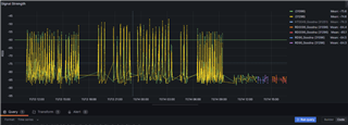
We have devices returning from the field which work ok for couple of weeks but then return with a 20 - 30dB drop in transmit power.

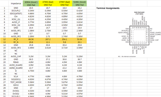
Replacing the CC1101 fixes the issue ( i.e nothing else wrong with the board) i.e we confirmed the damage is local to CC1101

If it is possible that PA is getting damaged. would TX-IF-CCA be able to detect the level of EM noise and prevent the device trying to transmit and potentially prevent damage.

As a side note is there a good explanation of CCA and the thresholds and how it all works?

  • Is it possible that these devices are being damaged in the field by an electrical over-stress such as ESD ?

  • Thanks, RGW.

    Anything is possible however the chance is low, product is professionally assembled and is used in two end uses both in a mining application.

    End-use A : 0% Failures.

    End-use B: Now approaching 100% on some installations. It works for some random time but then drops the transmit power.

    The one notable difference is that the A has a -8dB patch antenna encased with product. End-use B (failing)has a 3dB omni whip external to product.

    The RF circuit features a Balun filter that was in one of the dev kit applications notes and also features a DC blocking capacitors (50V rated)

    End-use B does sit in full weather on top of a moving vehicle (mining truck) however the failures never happen when the trucks aren't mobile i.e it could sit for months in the service bay without the failure occurring. Once in operation after few hours/days/weeks (i.e random) it drops that power. Repowering and reconfiguring the CC1101 doesn't solve the issue ..i.e there is some sort of physical damage/degradation in the CC1101. 

    Don't hesitate to ask more questions.

    Is RFI and at what level possible to damage the PA that is transmitting in presence of stronger RF input then it is capable of driving?

    Hopefully I'll be able to head to site to do some RF measurements and recordings.

  • Hi,

    Normally if there is any RFI or ESD damage, the receiver usually takes the first hit. The transmitter is quite robust with respect to RFI and ESD. 

    Could it be that the encased patch antenna has its own GND reference and is always matched. But the external whip antenna is detuned when mobile ?? Can you test with an external whip monopole antenna and an external dipole antenna to see if this if GND plane dependent ?

  • The whip antenna is free air design and doesn't rely on a ground plane, it's well matched and we're getting good PER on the system. I can confirm that the transmitter is degraded by 20 to 25dB. I haven't tested receiver as it's a broadcasting application. Would a damage to the receiver in any way affect the transmit power? what you see below is two sensors (green and yellow trace) located in close proximity (1m apart) transmitting for several days but then around 9am on 11/14 both devices drop the transmit power. (almost at same time)

    The product was retrieved and nothing else was damaged other than the CC1101 had the reduced transmit power.

    Replacing the CC1101 fixed the issue.  Placing the replaced CC1101 on a fresh board caused the board to transmit with lower power confirming the issue stays with CC1101.


  • Hi,

    If there is an RFI or ESD damage to the RF pins then the transmitter can also be affected as well. 

    When you have removed the CC1101 from the board. Can you measure the resistance of each pad to GND ? This could give some indication if the device has experienced any electrical over-stress.

    Is there any chance the voltage drops when the vehicle is mobile which could explain a decrease in output transmitted power ?

  • Hi 

    We de-soldered or removed the RF chips from the board, resulting in two good RF chips (highlighted in Green) and two damaged RF chips (low RSSI, highlighted in Yellow) for testing purposes.

    During the testing, we measured the resistance of each pin to GND pad. Please refer to the following testing results, 

    I have highlighted the resistance values in dark yellow, representing the measurement from RF_P and RF-N to GND. A notable difference is observed between good and damaged RF chips. The damaged RF chips exhibit significantly lower resistance. Could this indicate internal circuitry damages, such as to the LNA or PA, within the RF chips?

  • Hi,

    RF_P and RF_N are the most sensitive to an ESD strike especially if the ESD over-voltage was on the antenna. Due to the physical size of the antenna, it unfortunately takes the largest hit when receiving an over-voltage; which then goes to the RF_P and RF_N pads.

    So your measurements are showing a high probability that the units have been subjected to an ESD over-voltage. 

    Do you see this on many boards ?

    If you have a pi-match filter towards the antenna and there is a empty footprint to GND; then you could use the following component to protect against ESD: TPD1E0B04 The benefits of this component is it is only 0.15 pF capacitance which implies that you will not need to re-tune the antenna match whilst having ESD protection. This ESD protection footprint is available in 0402 and 0201.

  • Hi, Thanks for your reply.

    For an ESD strike, you mentioned that the ESD over-voltage may be on the antenna. So when we consider ESD it is about the stress that has overcome the insulation and has discharged static discharge which suggests a non-varying, i.e. not an AC waveform. The antenna we used is well-insulated and there are megaohms that are not even measurable with a digital multimeter. Our antenna is shown below, FW.95.B.SMA.M Taoglas | Mouser Australia 

    In addition, there is also a DC blocking capacitor that is 50V rated between GND and RF_N pad.

    To answer your question "Do you see this on many boards?"

    No, this is only happening on boards that are installed and have been operating near an AC drive (truck for illustrative purposes) https://www.cat.com/en_US/products/new/equipment/off-highway-trucks/mining-trucks/1000021630.html

    Currently, there is no spare footprint, but there is potential to replace the ground DC blocking capacitor with the ESD diode or mount it on top of it manually. 

  • Hi,

    The ESD protection needs to be positioned between the antenna / RF signal and the GND. It will not work with replacing the DC blocking cap with the ESD protection.