This thread has been locked.

If you have a related question, please click the "Ask a related question" button in the top right corner. The newly created question will be automatically linked to this question.

CC1312R: SmartRT Studio 7 Testing

Part Number: CC1312R
Other Parts Discussed in Thread: CC1190, UNIFLASH,

Dear Team,

Greetings of the day!

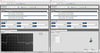
We have made a module having CC1312R1F3RGZ as our MCU & CC1190 as RF frontend IC. We basically want to test this module with SmartRF studio-7, but we are getting "Not able to open Device Control Panel" error when connected on the JTAG interface. Attaching screenshot for ref.

Although the JTAG interface works well when checked with Uniflash, I am able to read the configurations of the MCU. Even we are able to flash & debug the example programs for GPIO & UART all working well.

Hardware configuration:

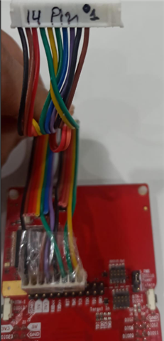
JTAG Connections: We are only using TCK, TMS, Reset, VCC & GND with the debugger.

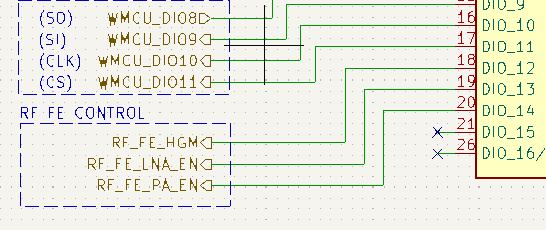
GPIO: 12,13,14 to control the RF-Front End

We need your support on these points.

1. How to resolve this problem so that we can further test our module with RF studio to check it's performance. 

2. How to configure the Configurations related to controlling the CC1190 front End IC into the RF studio so that it works automatically.

Please let me know if you need more details.

Thanks & Regards,

Harinder Singh

  • Hi Harinder,

    Could you do the following:

    1. Do a Mass erase of the flash in UniFlash under "Settings & Utilities"

    2. Update SmartRF Studio to the latest version

    3. Close all TI application and then open SmartRF Studio

    Please let me know it went.

    Also, how is your board powered?

    Regards,

    HG

  • Hi,

    We are basically using a launchpad to power up our board. We removed all the jumper between debugger & MCU on the launchpad, so that the native MCU on the launchpad becomes inactive & connected our board through jumper. We are sure about the connections as we are able to run & debug our examples codes in CCS. Attaching picture for your understanding about our setup, we connect our module on this white header (*marked as 14 Pin).

    Even the SmartRF Studio detects the chip but fails to connect, which is beyond my understanding. I have tried all the steps that you have mentioned but giving us the same problem. It seems like this method doesn't work for us.

    Please let me know if you need more details. We don't have CC1312R1 Launchpad to test this, kindly check this on your end as well if this problem repeats.

    Regards,

    Harinder

  • Hi Harinder,

    Sometimes we have seen in our lab that when the TMS and TCK cables are not separated, we get trouble with the JTAG because of cross talk between the two JTAG lines. I doubt that this could be the cause in your case since you are able to detect the device. However, just to be sure I recommend you to separate all 5 cable and see if it helps.

    Regards,

    HG

  • Hi Haiatullah,

    Greetings!!!

    Hope you doing good :) , well I don't think the crosstalk is the issue as we are able to program & debug the module without any issue every time

    It's something related to configuration of the soc/mcu in the smartRF studio, can you please confirm the same at your end with CC1312R1 launchpad.

    Please let me know if you need more details.

    Regards,

    Harinder Singh

  • Hi Harinder,

    I am not able to reproduce what you are seeing on my end. The device is detected, and I am able to open the control panel when powering one CC1312R LaunchPad from another LaunchPad.

    Regards,

    HG

  • Hi Haiatullah,

    It was lucky day for us today :) , able to make this work now with some hack!

    Basically the issue was with the reset in our case. The SmartRF was not able to reset the modules on its own (*let me know, if you have any input on this). So when I launch the controls on the SmartRF tool, I give a manual reset (*by pressing reset button present on launchpad) it detect & launch the testing window after that. 

    This is our reset circuit, please let me know if you find anything strange. Ideally the reset logic should work automatically as it is directedly connected to reset port on the debugger section of the launchpad (*ref. to previous image shared ) & I have checked for connectivity & logic level which seems to be fine.

    Please let me know if you need more information.

    Thanks & Regards,

    Harinder Singh

  • Hi Harinder,

    That is strange because I am able to open the device control panel even without connecting the reset line. And you reset circuitry looks fine to me.

    Regards,

    HG

  • Hi Haiatullah,

    Greetings!

    What I am able to understand from your last comment is that, you are able to connect with SmartRF studio over JTAG interface without using the Reset pin connected. 

    Correct me if I am wrong!

    Can you give more details on the following points:

    • Debugger Firmware version on the CC1312 launchpad that you have used
    • CC1312 complete part no. that you have used
    • Have you changed anything into the configuration from the default settings?

    Thanks & Regards

    Harinder Singh

  • Hi Harinder,

    When I opened the control panel without having the reset line connected earlier, the control panel opened. Now I tried again multiple times, sometimes it opens without a problem. However, it fails other times. When the error occurs, it will not be able to open the control panel until the debugger is disconnected and reconnected again. This indicates that there may be something wrong with the reset line of your board or the cable/cables connecting the debugger to your board.

    FYI - I am running the test with on a CC1312R1F3 device together with an XDS110 with FW rev. 3.0.0.26 and SmartRF Studio version 2.29.0.

    Regards,

    HG