This thread has been locked.
If you have a related question, please click the "Ask a related question" button in the top right corner. The newly created question will be automatically linked to this question.
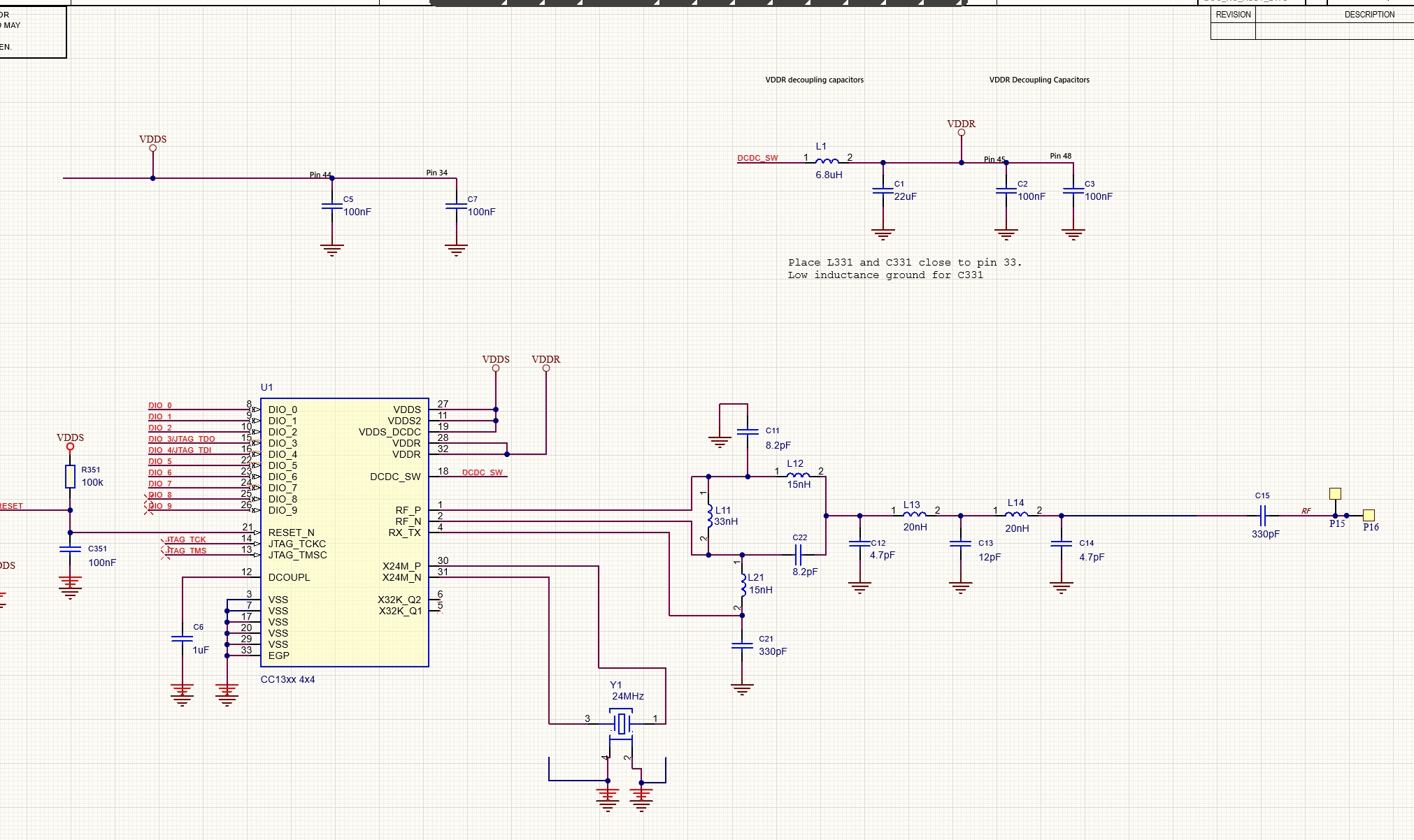
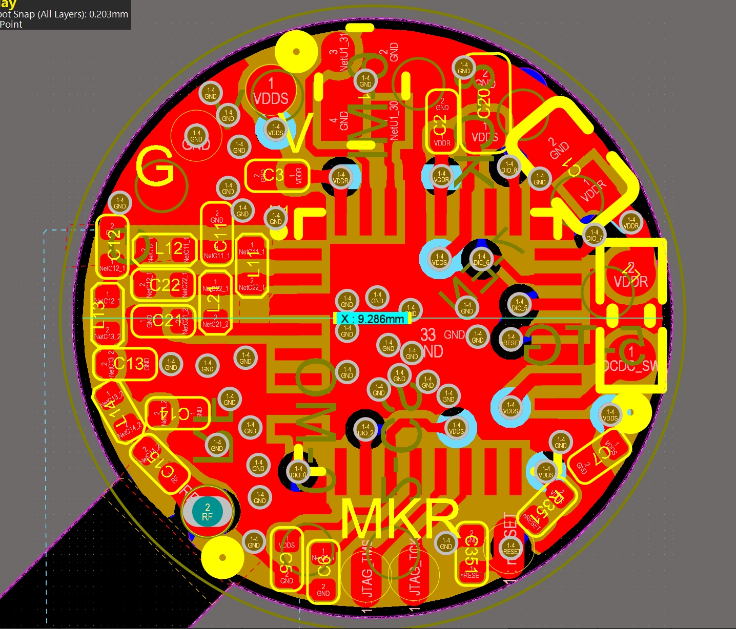
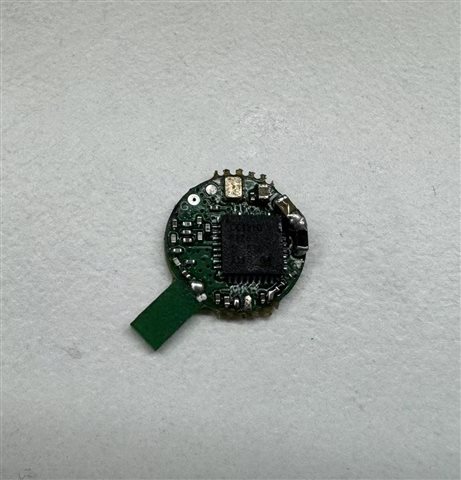
This is my schematic design and PCB design.
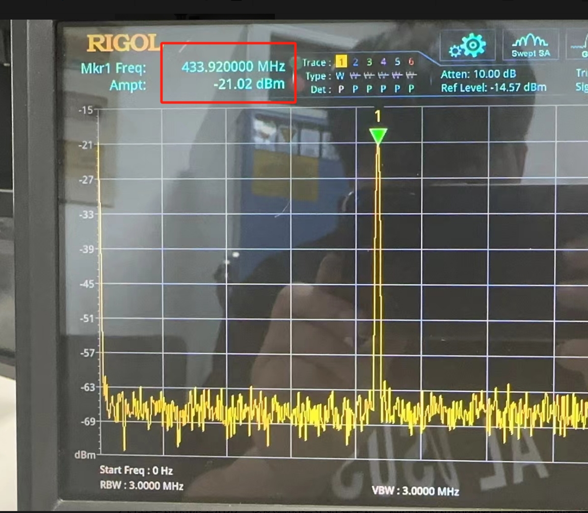
When the software sets the RF power to 4dmb, the actual signal strength measured using a spectrum analyzer is only -20dbm.
Where can I improve my design?
Hi,
accessing images from external file sharing sites is an issue for us. Could you please upload the images directly to E2E?
Hi A B,
I noticed you don't have the 22uF capacitor on VDDS_DCDC in your schematic and a 100nF cap is missing. There should be a 100nF cap for each VDDS pin. Were this component intentionally left out?
I see you don't have an RF connector on your board. How exactly are you measuring the output power? Are you soldering a semi rigid cable?
Are you using Smart RF studio to set the device to continuous Tx or how are you transmitting the carrier wave?