This thread has been locked.

If you have a related question, please click the "Ask a related question" button in the top right corner. The newly created question will be automatically linked to this question.

REGARDING CC2530 TIMER 1 CONFIGURATION AND TIMER 1 INTERRUPT HANDLING ROUTINE

Hello,

I am trying to run a simple program to test the 32 MHz timer. (Clock speed set to 250 KHz and tick speed set to 32 MHz, clock running in free run mode).

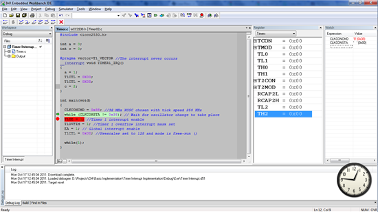
Below is the code entered into IAR Embedded Workbench:

#include<ioCC2530.h>
int a = 0;
int c = 0;
#pragma vector=T1_VECTOR //The interrupt never occurs
__interrupt void TIMER1_IRQ()
{
  a = 1;
  T1CTL = 0X00;
  T1CTL = 0X0D;
  c = 2;
}
main()
{
  T1IE = 1; //Timer 1 interrupt enable
  T1OVFIM = 1; //Timer 1 overflow interrupt mask set
  CLKCONCMD = 0x07; //32 MHz XOSC chosen with clock speed 250 MHz
  T1CTL = 0x0D; //Prescaler set to 128 and mode is free-run
     while(1);
}
Is the above program correct? I expected the interrupt to triggered after 33 seconds but the flags T1STAT.OVFIF and IRCON.T1IF are not being set indicating that the timer isn’t working. How shall we fix this? Also, what is the difference between clock speed and tick speed?


Thank you

SIDDHARTH


  • In one of these SoC parts the data sheet is incorrect and only the CCR0 interrupt occurs, not the overflow.  I would suggest running the code in the debugger, open up a register window and select the timer 1 register set.  As you step through the code you should see the counter changing (you may want to set the prescaler to divide by 1 for this).  When it reaches the end of the loop, watch the interrupt flags to see which one actually gets set and then use that one.

    Sometimes empirical evidence is worth a thousand pages of spec sheets!  =D

    Jim Noxon

  • In this case, the timer is set in free-running mode, and then the overflow interrupt works. In modulo mode, the overflow interrupt is not asserted, but this is documented correctly in the user guide. The documentation on the overflow interrupt is however incorrect on Timer 3 and 4.

    There are a couple of other problems with your code.

    First, you should add EA = 1; to set the global interrupt enable flag.

    Second, you reduce the system clock speed. However, that is not supported with debugging. You can however reduce only the tick speed for the timers and not the system clock speed. To do that, set the TICKSPD bits in CLKCONCMD to 111 and set CLKSPD  to 000.

    Third, when you switch oscillators, I recommend that you wait for the clock switch to complete.

    All in all, change your main routine to the one below, and it should work.

    int main(void)
    {
      CLKCONCMD = 0x038; //32 MHz XOSC chosen with tick speed 250 MHz
      while (CLKCONSTA != 0x38); // Wait for oscillator change to take place
      T1IE = 1; //Timer 1 interrupt enable
      T1OVFIM = 1; //Timer 1 overflow interrupt mask set
      EA = 1; // Global interrupt enable
      T1CTL = 0x0D; //Prescaler set to 128 and mode is free-run
      while(1);
    }

  • hec said:
    Third, when you switch oscillators, I recommend that you wait for the clock switch to complete.


    I put a breakpoint immediately after  while (CLKCONSTA != 0x38); However, even after 4-5 minutes of execution, the code never broke out of the loop. Please help.

    Thanks,

    John

  • The switch should happen in less than 500 us. What is the value of CLKCONSTA when you break?

    Note that this statement tries to switch to the 32 KHz XOSC, and this can only be done while the system is running on the 16 MHz RCOSC. If you do this clock switch right out of reset, it should work, but if you have already switched to the 32 MHz XOSC, but not the 32 kHz XOSC, you need to modify the instructions. If you don't want to use the 32 kHz XOSC, you can write CLKCONCMD = 0xB; and while (CLKCONSTA != 0xB8); instead. If you want to use the 32 kHz XOSC, you should enable it in the first clock switch operation after reset.

  • hec said:
    What is the value of CLKCONSTA when you break?


    The value is 0. The screenshot shows the condition on break.


  • Are you sure that you are running on the target and not using the IAR simulator? The simulator does not support hardware register simulation. Under Project->Options, go into Debugger and make sure Texas Instruments is selected under Driver:


  • That was it! I was using the simulator indeed.

    Thanks hec.

  • Hello guys,

    My timer1 is not working properly and it's driving me crazy. The problems is when I set an interrupt on a channel of the Timer1 (I want on compare) it goes to the interrupt even the timer value is not as expected. Here is my code and attached is a print screen of the registers. I expected the T1CNT == T1CC0 but, as you can see, it's not. (Ofcourse EA = 1)

    Many thanks and hope for a solution,

    Mircea

    // init timer

    // Set prescaler to 128 halt timer, free running mode
    T1CTL = 0x0C;

    // Initial start value
    T1CNTH = 0x00;
    T1CNTL = 0x00;

    // Disable the overflow interrupt - this will never be used
    T1OVFIM = 0;

    // clear all interrupt flags
    T1STAT = 0;

    // Set period
    T1CC0L = LO_UINT16(timeout_ticks);
    T1CC0H = HI_UINT16(timeout_ticks);
    // set IM: interrupt mask
    set_flag(T1CCTL0,BIT6 + BIT2);

    T1CTL = 0x0D;

    T1IE = 1;

    // interrupt

    #pragma vector = T1_VECTOR

    #pragma vector = T1_VECTOR
    __interrupt void Timer1_ISR(void)
    {
    // channel 0
    if (is_flag_set(T1STAT,BIT0))
    {

    ...

    }

    }

  • : Please re-post in a 2.4 GHz forum.