This thread has been locked.

If you have a related question, please click the "Ask a related question" button in the top right corner. The newly created question will be automatically linked to this question.

CC1020: RF sensitivity issue

Part Number: CC1020

Hi. I have designed two CC1020 PCB's for UHF 433 MHz radio communication. One board is used as transmitter & other as receiver. I have configured both in synchronous NRZ mode with 4.8k baud. The receiver is only able to demodulate data accurately till -92 dBm. But the datasheet spec is -112 dBm. I have tried changing VGA settings, deviation & filter bandwidth settings. Changed loop filter components to 12.5 kHz & 25 kHz channel spacings. Matching network impedance is also fine.  But same issue exists. How can I improve the sensitivity?

  • Hi,

    • Please review SWRA603 (Debugging Communication Range): https://www.ti.com/lit/swra603
    • Are you using SmartRF Studio to evaluate the RF settings?
    • Are these conducted measurements?
    • Please share your exact settings (including resolution bandwidth) and your measurement setup for us to be able to better assist you.

    Regards,

    Zack

  • Hello. Thanks for the reply. The test is conducted mode at 433 MHz with GFSK NRZ mode 4.8kbaud. I don't have windows xp/7 to use Smart RF studio v6.0. So register values are given by manual calculations from datasheet. Please find the attached images as mentioned below 

    • Block diagram of test set up
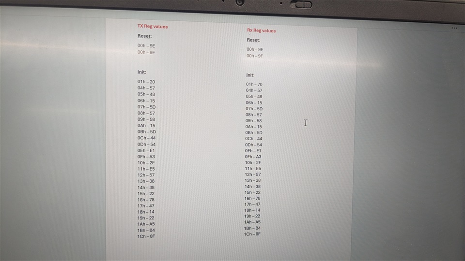
    • Register values for initialisation
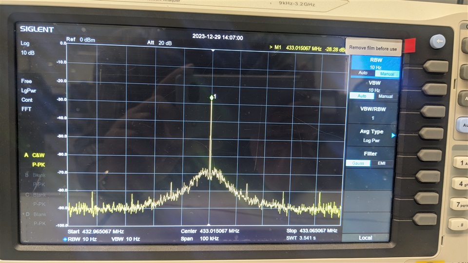
    • Unmodulated carrier without attenuation for 10Hz RBW
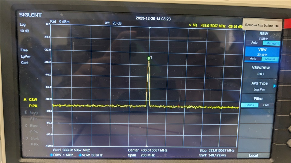
    • Unmodulated carrier without attenuation for 1MHz RBW
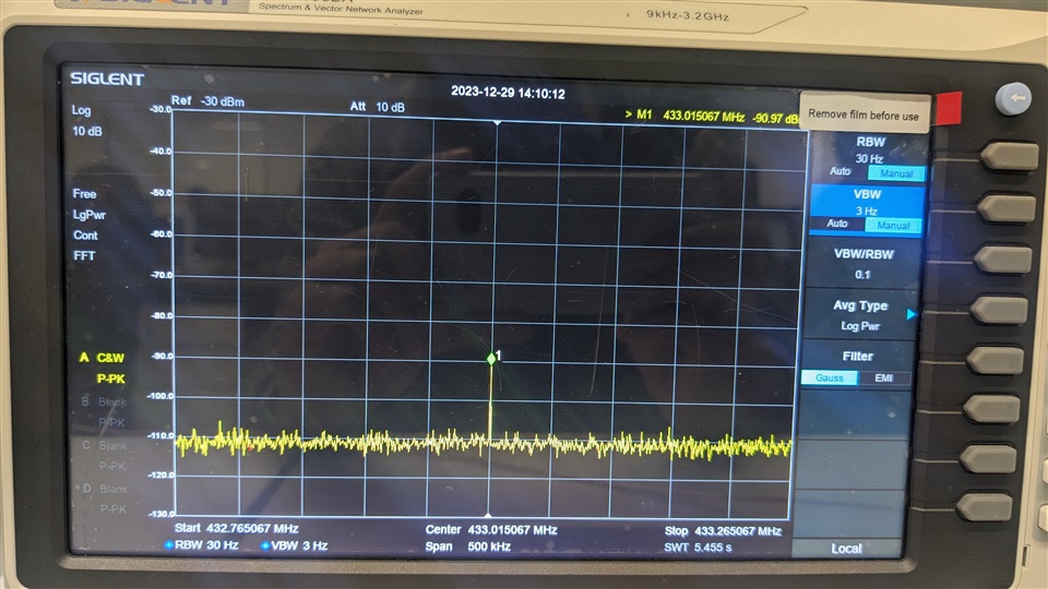
    • Unmodulated carrier with 65dB attenuation
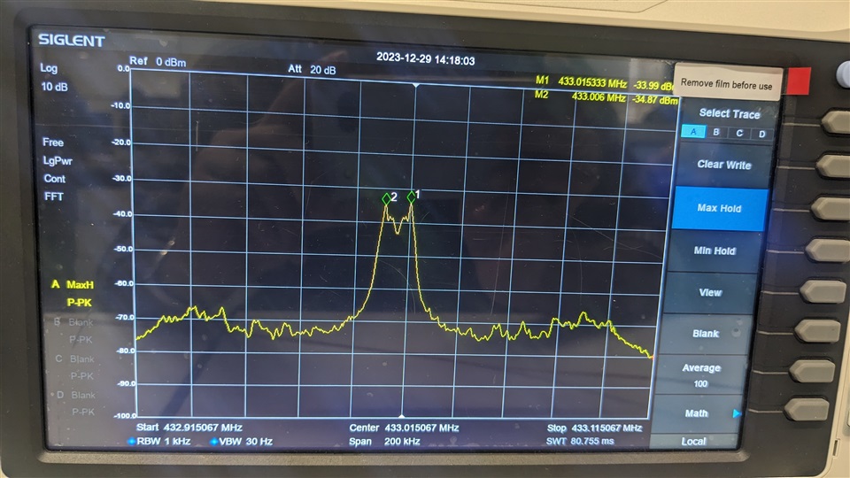
    • Modulated carrier without attenuation
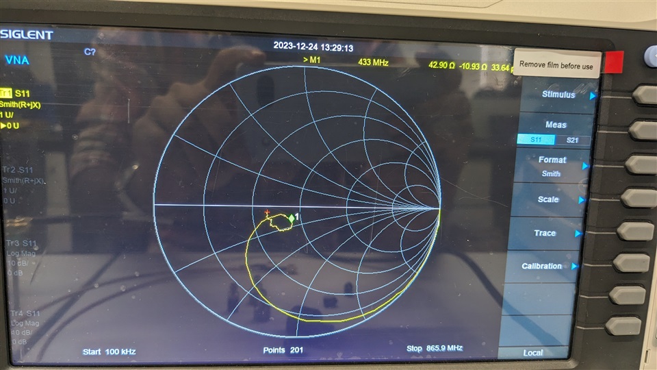
    • Matched input impedance of receiver path S11 in VNA 

    If you can access Smart RF studio please share any change in reg values for RX gain for the same specs.

  • Please can you provide the register settings in a text format? It is harder to compare them if it is just a screenshot - thank you.

    Regards,

    Zack

  • Reg    Data - Rx card register configuration:

    00 h - 01

    01 h - 70 (Initialisation) & 50 (Setup Rx)

    04 h - 57

    05 h - 48

    06 h - 15

    07 h - 5D

    08 h - 57

    09 h - 58

    0A h - 15

    0B h - 5D

    0C h - 44

    0D h - 54

    0E h - E1

    0F h - A3

    10 h - 2F

    11 h - E5

    12 h - 57

    13 h - 38

    14 h - 38

    15 h - 22

    16 h - 78

    17 h - 47

    18 h - 14

    19 h - 22

    1A h - A5

    1B h - B4

    1C h - 00

    For Tx register configuration: 

    • 00 h = C1
    • 01 h = 20 
    • 1C h = 01
    • Remaining registers are similar to Rx configuration 
    • Registers which are not mentioned are set to default value (02 h,03 h etc)
  • Hello Sir. Could you please provide technical assistance in solving this issue of sensitivity of CC1020 ? 

    • I need one clarification.Unmodulated carrier power is -26 dBm.
    • Modulated carrier power is -36 dBm (10 dBm less than unmodulated).
    • So if 65 dB attenuation is given between Tx & Rx path, the received power level at RF in of transceiver to be considered is -91 dBm or -101 dBm. 
    • Since we will be sending data only modulated carrier will be at RF in which is -101 dBm.
    • In this case, am I losing just 11 dB of sensitivity which is -112 dBm as per datasheet ?
    • Or should I consider received power level as -91 dBm (unmodulated) & the loss in sensitivity is 21 dB.