Other Parts Discussed in Thread: CC1101,
Hi everyone,
I'm working on a project that utilizes the CC1101 transceiver in asynchronous serial mode.
Due to compatibility requirements with existing devices, my client specifies the use of the CC1101-Q1 in async serial mode.
Configuration:
I've configured the CC1101 according to the following setup:
- GDO0 on the transmitter: Data Input
- GDO1 on the receiver: Serial Data Output
This configuration allows me to observe the signal using an oscilloscope.
With the transmitter powered on and transmitting at a data rate of 1.2 kBaud, the received signal on GDO1 appears relatively normal:

However, when the transmitter is powered off, the received signal exhibits significant noise (see image below):

likely caused by environmental factors . This is the first issue.
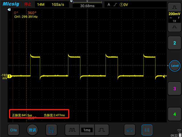
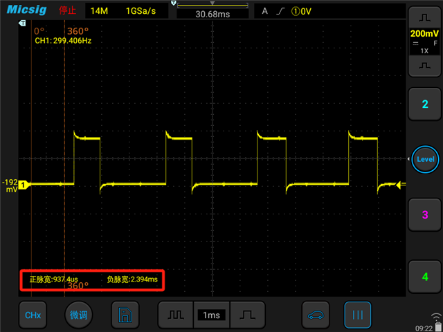
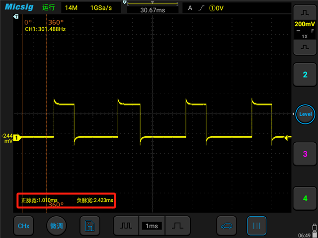
Another issue is the received signal appears to have unstable pulse widths.
The transmitted signal on TX GDO0 has a high-to-low pulse ratio of 1:3, controlled by an MCU GPIO pin.
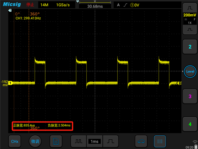
However, the received signal on GDO1 exhibits variations in pulse width, as shown in the screenshots below
(4 images representing the waveform at different moments).
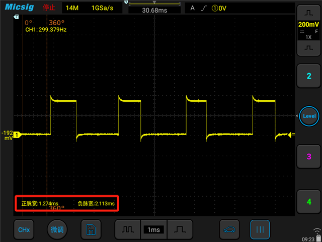
Problem Description:
- Despite the absence of a transmitted signal, noise is still present
- The received signal exhibits significant fluctuations in pulse width compared to the transmitted signal, regardless of the carrier frequency used (433 MHz, 868 MHz, 915 MHz).
Concerns:
-
MCU Processing: This instability could potentially hinder the ability of the MCU to process the signal accurately, leading to increased complexity in the processing algorithms and potentially resulting in data errors.
-
Development Experience: As someone new to transmitter development, I'd like to confirm the validity of these concerns.
Solutions:
If the concerns are reasonable, are there any methods to
1. reduce noise
Carrier Sense Threshold: I'm considering using Carrier Sense Threshold to mitigate noise, but the numerous registers mentioned in the datasheet are overwhelming. While I've been reviewing the datasheet and forum posts, I'm short on time. Here's where your expertise could be of great help:
- Could you recommend some practical steps I can take to get started implementing Carrier Sense Threshold for my specific situation?
- Are there alternative solutions that might be more efficient in this case?
2. enhance the stability of the pulse width
- Are there any methods to enhance the stability of the pulse width? If so, could you provide detailed steps on how to achieve this?
I would be grateful if you could provide some detailed steps. Thank you in advance!


