


Tool/software:
Dear TI expert,
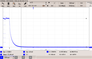
When i use CC1310 work in standyby mode , the VDDR decouple capacitor is 10uF,VDDR volatge will be subjected to external electromagnetic interference, and the voltage will drop to 0V , the MCU is died ,need to reset .
So i test the VDDR may max output 50uA in standby mode , when the load is over 50uA ,the VDDR will be drop to 0V ,and the MCU is died.
The VDR voltage started to fluctuate, and when I increased the load by 50uA.

When the current is over 50uA, the VDDR voltage is drop to 0V .
So ,if i want to improve the VDDR load current ,I think it's more resistant to interference.
how to set the VDDR register? Could you help to provide how to set C2 [23:20],C1[19:16],MAX_PER_M [15:11],MAX_PER_E [10:8],PER_M[7:3],PER_E[2:0]?
Thank you very much.
|
寄存器(RECHARGECFG) |
参数值 |
描述 |
|
ADAPTIVE_EN [31] |
1 |
Enable adaptive recharge |
|
C2 [23:20] |
0x0A(TI 默认值) |
Gain factor for adaptive recharge algorithm period_new=period * ( 1+/-(2^-C1+2^-C2) ) Valid values for C2 is 2 to 10 |
|
C1[19:16] |
0x04(TI 默认值) |
Gain factor for adaptive recharge algorithm period_new=period * ( 1+/-(2^-C1+2^-C2) ) Valid values for C1 is 1 to 10 |
|
MAX_PER_M [15:11] |
0x1C(TI 默认值) |
This register defines the maximum period that the recharge algorithm can take, i.e. it defines the maximum number of cycles between 2 recharges. The maximum number of cycles is specified with a 5 bit mantissa and 3 bit exponent: MAXCYCLES=(MAX_PER_M*16+15)*2^MAX_PER_E This field sets the mantissa of MAXCYCLES |
|
MAX_PER_E [10:8] |
0x07(TI 默认值) |
This register defines the maximum period that the recharge algorithm can take, i.e. it defines the maximum number of cycles between 2 recharges. The maximum number of cycles is specified with a 5 bit mantissa and 3 bit exponent: MAXCYCLES=(MAX_PER_M*16+15)*2^MAX_PER_E This field sets the exponent MAXCYCLES |
|
PER_M[7:3] |
依据MCU芯片出厂参数设置计算 |
Number of 32 KHz clocks between activation of recharge controller For recharge algorithm, PERIOD is the initial period when entering powerdown mode. The adaptive recharge algorithm will not change this register PERIOD will effectively be a 16 bit value coded in a 5 bit mantissa and 3 bit exponent: This field sets the Mantissa of the Period. PERIOD=(PER_M*16+15)*2^PER_E |
|
PER_E[2:0] |
依据MCU芯片出厂参数设置计算 |
