Tool/software:
Hello,
One year ago, I got some great help here migrating an older ATA5760-based FSK receiver to a CC110L-based receiver.
However, after ordering a batch of 50 new receivers, it turned out that not all transmitters were recognized by all receivers.
I found that this was due to variation in the actual transmitter frequencies - especially the older transmitters are not very accurate, and their nominal frequency (ideally 869.200 MHz) can vary as much as 50 kHz. Also, the difference between the lower and higher FSK frequency (the deviation) can vary between 25 kHz and 40 kHz.
The fact that these variations are giving trouble suggest that the CC110L settings are not quite optimal.
Question: is it possible to determine optimal settings for the CC110L from the range of transmitter frequencies that I measured?
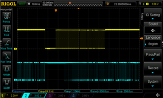
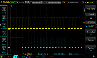
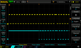
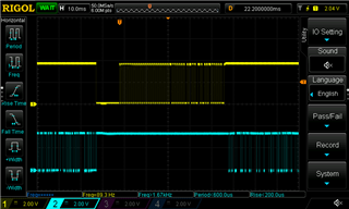
Transmitters use 2-FSK to transmit a Manchester-encoded signal with a 1 kHz symbol rate; the following are the transmitter FSK frequencies as measured for 3 transmitters:
TX1: 869.193 MHz - 869,220 MHz (d = 27 kHz)
TX2: 869.230 MHz - 869.270 MHz (d = 40 kHz)
TX3: 869.234 MHz - 869.264 MHz (d = 30 kHz)
I found that the receiver base frequency should not be too low - 869.239258 MHz (using SmartRF Studio 7) works OK for all three, but with 869.229370 MHz, TX3 is not recognized, and if I go lower still, TX2 also fails. Does this mean that the RX base frequency should always be somewhat higher than the highest lower FSK frequency? So in this case the lower frequency of TX3 (869.234 MHz)?
On the other hand, 869.268921 MHz seems just a bit too high for TX1 - which is not what I would expect given the RX Filter BW of 168.750000 kHz.
Some other relevant receiver parameters:
IF: 395.50781 kHz
Deviation: 29.663086 kHz
These latter three were more or less the result of guesswork and a lot of trial-and-error - but frankly, I'm not very good at this digital RF stuff, and it is unclear to me how the CC110L recognizes and decodes what is basically a slightly varying UHF signal. Yes, I understand about a local oscillator, a mixer and a resulting IF signal with a certain filtered bandwidth - but only how these work in old, analog circuits, where I can actually put my probe at every stage to measure and see what is happening.
So could anyone tell me how these receiver settings could be further optimized, given the range of TX parameters?
ADDENDUM:
I was just going over the numbers again, and I think that I must be doing something wrong:
- With base frequency = 869.199707 MHz (very close to the nominal base frequency), TX3 and TX3 are not recognized
- With base frequency = 869.239258 MHz (so just 40 kHz higher), all three are recognized
- With base frequency = 869.268921 MHz (so another 30 kHz more) TX1 already fails.
So just 30 kHz difference with respect to a base frequency of 869-something MHz = 35 ppm can make the difference between a working and a failing setup. Surely this can't be right? Because according to paragraph 4.9 in the CC110L datasheet, the crystal oscillator already has a typical tolerance of ±40 ppm.
This 30 kHz is also way less than the 168.75 kHz bandwidth that I set. Could someone explain to me what might be going on? I must be overlooking something pretty fundamental here.
Thanks again already, regards,
Richard