This thread has been locked.

If you have a related question, please click the "Ask a related question" button in the top right corner. The newly created question will be automatically linked to this question.

CC1352P7: LP-CC1352P7-1

Part Number: CC1352P7

Tool/software:

Hi!

I am developing hardware using the CC1352P7 to run Wi-SUN. I used the Launchpad LP-CC1352P7-1: 868/915 MHz up to 20 dBm, 2.4 GHz up to 5 dBm as a reference.

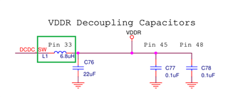
I just didn’t include the parts marked in green in my schematic:

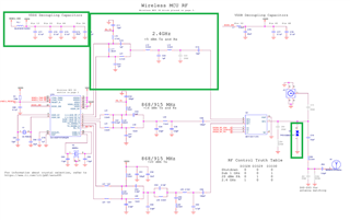
Could this cause connection issues?
Below you can see it in my schematic:

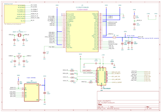
(1) I reduced the resistance of R18 to 10K.


(2) I removed the capacitances of X1A (because the circuit couldn’t maintain ifconfig up and wisunstack start).

(3) Now I can keep ifconfig up and wisunstack start, but I can't make my device connect to another.


(4) Using the RF-star module with CC1352P7 connected to my antenna, I achieved a stable connection.


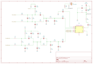
(5) How can I force communication through the 14 dBm differential pair? I want to check if the issue is with the soldering of the “SKY13317-373” chip.
Any debugging tips?

Attached are the copper layer plots of my PCB and also the schematic:

CC1352P7.zip


  • Hi Vinicius,

    Not having the VDDS decoupling capacitors may be causing the device to reset when an RF transmission is started. All of the capacitors from the reference design and the ferrite bead (FL1) should be included in your design. You can probe VDDS with a oscilloscope to see if your issues are being caused by VDDS brown-out.

    Now, if you can make wisunstack start after removing the crystal load capacitors, then the issue could also be that the crystal wasn't starting up due to the load capacitance being high. Which crystal are you using? Do you have the internal cap array enabled or disabled?

    Have you connected your board to a spectrum analyzer to see if you are getting an outptut and it's at the right frequency?

    Have you tried using the packet Tx example on you board and check if you can receive packets on the launchpad using SmartRF Studio?

  • Hi!

    First, thank you for your feedback!

    I made a mistake by using capacitances that were too high on the crystal, which prevented oscillation. Now, I’ve added a 6.8pF capacitance, and everything works as expected.

    Using a spectrum analyzer together with SmartRF Studio, I was able to make the device generate a signal at 915 MHz as expected. However, when I requested a constant RX view, the device would freeze and stop responding. I suspected the RF power supply.

    I found that I had used the wrong inductance for the VDDR circuit (1.68V). After changing it to 10 uH, the circuit showed the RX constantly, and I was able to see that the antenna communication happened as expected.

    Finally, I ran a Wi-SUN code and was able to get two devices to connect.