This thread has been locked.

If you have a related question, please click the "Ask a related question" button in the top right corner. The newly created question will be automatically linked to this question.

CC1354P10: 2.4GHz Custom protocol use

Part Number: CC1354P10

Tool/software:

Hello EE, 

I was trying to use the CC1354P10 radio in 2.4GHz band with custom protocol.

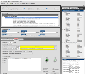
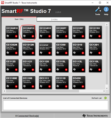
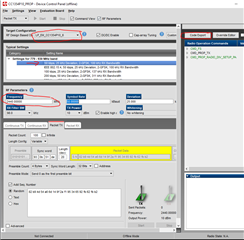
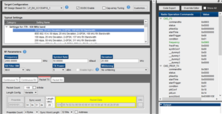
When I try to configure the radio using Smart Rf Studio > Proprietary, and then selected an available standard radio settings option and change the Frequency to 2400MHz. The moment I change the frequency, the PA option was greyed out. Is there anything I am missing here ?

Can 2.4GHz radio PA used with the proprietary protocol settings? 

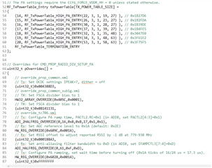
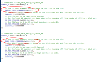
If yes, can you please help me in configuring the PA table? 2.4GHz 5dBm is working well for me. Thanks. 

Satya Raji

  • Hi Satya,

    This is due to the "RF Design Based On" selected. In the shared screenshot you have selected the LP_EM_CC1354P10_1

    The LP-EM-CC1354P10-1 has the +20 dBm PA configured for 868/915 MHz operation. The LP-EM-CC1354P10-6 is configured for 2.4 GHz, +10 dBm or +20 dBm output (the +10 dBm BOM is mounted on the shipped boards so +20 dBm operation requires changing the BOM): https://www.ti.com/tool/LP-EM-CC1354P10 

    You will want the LP_EM_CC1354P10_6 (which is configured for 2.4 GHz, +10 dBm output) or LP_EM_CC1354P10_6, 20DBM RF design selected. With SmartRF Studio 7, v2.31.0 I tried changing the output frequency to 2400 MHz and it worked as expected.

    Regards,

    Zack

  • Hi Zack, 

    Thanks for the information.

    My hardware has the PA on 2.4GHz. I have generated the "ti_radio_config.c" Using CC1354P10_6, then I have enabled the required GPIOs to keep the Sky chip to PA mode.

    Now my question is how to configure the CC1354 to output the 2.4GHz data through the TX_20DBM_P, and TX_20DBM_N pins? I guess by default the PA would be assigned to SUBGIG, if I would like to change that to 2.4GHz, what are the registers/structures to be modified?

    Any help would be highly appreciated. 

    Regards,

    Satya Raji   

  • Hi Satya,

    Do you mean how to configure the +20 dBm PA in CCS? You will need to select the LP-EM-CC1354P10-6 design (+10 dBm or +20 dBm as required). I can loop in a SW colleague to assist with this if it is not clear.

    When you mention "keep the Sky chip to PA mode" are you referring to a Skyworks FEM (I don't have the context for this design)?

    If so, you wouldn't need +20 dBm output from the CC1354P10; the application would typically use either the +20 dBm PA from the CC1354P10 or use the Sub-1 GHz output of the CC1354P10 as the input to an external FEM (as +20 dBm input would likely damage the FEM). An external FEM would be used to achieve greater than +20 dBm (I assume).

    Regards,

    Zack

  • Hello Zack,

    I can't find any schematics of CC1354P10_6 kit.

    I have a Skyworks FEM on the board, exactly the same circuit as CC1354P10_1. Looks like the PA route can be configured to either of the SubGig or 2G4 with some power settings and PA power table in the "ti_radio_config.c".

    Now with all these looks like the transmitter was tuned for 2G4 on my HW. I can see the spectrum analyzer was showing super strong signal when I use the PA and without PA table I am seeing normal signal at the frequency set. 

    But for some reason my receiver is not working when I use the same settings as the transmitter (2G4 with PA).

    By the way, can you please help me understand the power settings ?

    This

    and this area. 

    Appreciate your time. 

    Satya Raji

  • Hi Satya,

    The schematics are found in the design files: LP-EM-CC1354P10-6 (SWRC391): https://www.ti.com/lit/zip/swrc391

    There are separate BOMs for +10 dBm and +20 dBm output power at 2.4 GHz. +10 dBm output power uses VDDR for the bias voltage so has a significantly reduced current consumption. 

    I misread your original post, I see you are talking about the Skyworks SP3T RF switch. You can see the DIO configuration in SmartRF Studio 7 under Settings -> Custom Target Configuration

    For RX operation, the RF switch needs to be set to the 2.4 GHz path (not the PA path, which is for TX only): DIO34. The 2_4_GHZ_RF ports are used for RX at 2.4 GHz.

    You can confirm the required DIO settings using the SKY13317-373 datasheet and comparing to the LP-EM-CC1354P10-6 schematic: https://www.skyworksinc.com/-/media/SkyWorks/Documents/Products/301-400/SKY13317-373LF_200914L.pdf


    The DIO configuration is correct in SmartRF Studio when the output frequency is set to 2400 MHz and one of the LP-EM-CC1354P10-6 designs is selected:

    If you export these settings from SmartRF Studio this should work as expected.

    Regards,

    Zack

  • Hi Zack,

    Thanks for the inputs. The transmit part of 20dBm 2.4GHz looks good, I am still working on the receiver part. Will update my findings soon. Regards,

    Satya

  • Hello Zack,

    I did the required changes to the ti_radio_config.c and .h files, and then switching external antenna switch according to the band I've selected.

    For some reason, I am not seeing much difference in the rssi (at the receiver/setup Tx and Rx at fixed location thorough out this experiment) values when I enable and disable the PA path.

    I checked the Tx power with a spectrum analyzer (at a fixed location) too, showing -24 and -26dbm with and without the PA enabled. On the Rx side, I always on the regular 2.4GHz path. 

    Below is my code. Can you please go through and let me know if I miss anything ?


    /*
     *  ======== ti_radio_config.c ========
     *  Configured RadioConfig module definitions
     *
     *  DO NOT EDIT - This file is generated for the CC1354P10RSK
     *  by the SysConfig tool.
     *
     *  Radio Config module version : 1.18.0
     *  SmartRF Studio data version : 2.30.0
     */
    
    #include "ti_radio_config_2400.h"
    #include DeviceFamily_constructPath(rf_patches/rf_patch_cpe_multi_protocol.h)
    
    
    // *********************************************************************************
    //   RF Frontend configuration
    // *********************************************************************************
    // RF design based on: LP_EM_CC1354P10_1
    
    // TX Power tables
    // The RF_TxPowerTable_DEFAULT_PA_ENTRY and RF_TxPowerTable_HIGH_PA_ENTRY macros are defined in RF.h.
    // The following arguments are required:
    // RF_TxPowerTable_DEFAULT_PA_ENTRY(bias, gain, boost, coefficient)
    // RF_TxPowerTable_HIGH_PA_ENTRY(bias, ibboost, boost, coefficient, ldoTrim)
    // See the Technical Reference Manual for further details about the "txPower" Command field.
    // The PA settings require the CCFG_FORCE_VDDR_HH = 0 unless stated otherwise.
    
    // 2400 MHz, 5 dBm
    /*RF_TxPowerTable_Entry txPowerTable_2400_pa5[TXPOWERTABLE_2400_PA5_SIZE] =
    {
        {-20, RF_TxPowerTable_DEFAULT_PA_ENTRY(7, 3, 0, 0) }, // 0x00C7
        {-18, RF_TxPowerTable_DEFAULT_PA_ENTRY(9, 3, 0, 0) }, // 0x00C9
        {-15, RF_TxPowerTable_DEFAULT_PA_ENTRY(12, 3, 0, 4) }, // 0x08CC
        {-12, RF_TxPowerTable_DEFAULT_PA_ENTRY(10, 2, 0, 4) }, // 0x088A
        {-10, RF_TxPowerTable_DEFAULT_PA_ENTRY(18, 3, 0, 0) }, // 0x00D2
        {-9, RF_TxPowerTable_DEFAULT_PA_ENTRY(14, 2, 0, 7) }, // 0x0E8E
        {-6, RF_TxPowerTable_DEFAULT_PA_ENTRY(19, 2, 0, 11) }, // 0x1693
        {-5, RF_TxPowerTable_DEFAULT_PA_ENTRY(21, 2, 0, 11) }, // 0x1695
        {-3, RF_TxPowerTable_DEFAULT_PA_ENTRY(38, 3, 0, 14) }, // 0x1CE6
        {0, RF_TxPowerTable_DEFAULT_PA_ENTRY(30, 1, 0, 21) }, // 0x2A5E
        {1, RF_TxPowerTable_DEFAULT_PA_ENTRY(35, 1, 0, 25) }, // 0x3263
        {2, RF_TxPowerTable_DEFAULT_PA_ENTRY(22, 0, 0, 35) }, // 0x4616
        {3, RF_TxPowerTable_DEFAULT_PA_ENTRY(29, 0, 0, 46) }, // 0x5C1D
        {4, RF_TxPowerTable_DEFAULT_PA_ENTRY(41, 0, 0, 64) }, // 0x8029
        {5, RF_TxPowerTable_DEFAULT_PA_ENTRY(63, 0, 0, 0) }, // 0x003F
        RF_TxPowerTable_TERMINATION_ENTRY
    };*/
    
    // 2400 MHz, 20 dBm
    RF_TxPowerTable_Entry txPowerTable_2400_pa20[TXPOWERTABLE_2400_PA20_SIZE] =
    {
        {14, RF_TxPowerTable_HIGH_PA_ENTRY(22, 3, 1, 19, 27) }, // 0x1B27D6
        {15, RF_TxPowerTable_HIGH_PA_ENTRY(26, 3, 1, 23, 27) }, // 0x1B2FDA
        {16, RF_TxPowerTable_HIGH_PA_ENTRY(30, 3, 1, 28, 27) }, // 0x1B39DE
        {17, RF_TxPowerTable_HIGH_PA_ENTRY(37, 3, 1, 39, 27) }, // 0x1B4FE5
        {18, RF_TxPowerTable_HIGH_PA_ENTRY(32, 3, 1, 35, 48) }, // 0x3047E0
        {19, RF_TxPowerTable_HIGH_PA_ENTRY(34, 3, 1, 48, 63) }, // 0x3F61E2
        {20, RF_TxPowerTable_HIGH_PA_ENTRY(53, 3, 1, 58, 63) }, // 0x3F75F5
        RF_TxPowerTable_TERMINATION_ENTRY
    };
    
    //*********************************************************************************
    //  RF Setting:   Custom (100 kbps, 50 kHz Deviation, 2-GFSK, 350 kHz RX Bandwidth (Preview settings))
    //
    //  PHY:          custom2400
    //  Setting file: setting_tc900_custom.json
    //*********************************************************************************
    
    // PARAMETER SUMMARY
    // RX Address Mode: No address check
    // Frequency (MHz): 2440.0000
    // Deviation (kHz): 50.0
    // Packet Length Config: Variable
    // Max Packet Length: 255
    // Preamble Count: 4 Bytes
    // Preamble Mode: Send 0 as the first preamble bit
    // RX Filter BW (kHz): 349.7
    // Symbol Rate (kBaud): 100.000
    // Sync Word: 0x930B51DE
    // Sync Word Length: 32 Bits
    // TX Power (dBm): 5
    // Whitening: No whitening
    
    // TI-RTOS RF Mode Object
    RF_Mode RF_prop =
    {
        .rfMode = RF_MODE_PROPRIETARY_2_4,
        .cpePatchFxn = &rf_patch_cpe_multi_protocol,
        .mcePatchFxn = 0,
        .rfePatchFxn = 0
    };
    
    // Overrides for CMD_PROP_RADIO_DIV_SETUP_PA
    uint32_t pOverrides[] =
    {
        // override_tc900.json
        // DC/DC regulator: In Tx, use DCDCCTL5[3:0]=0x3 (DITHER_EN=0 and IPEAK=3).
        (uint32_t)0x00F388D3,
        // Tx: Configure PA ramp time, PACTL2.RC=0x2 (in ADI0, set PACTL2[4:3]=0x2)
        ADI_2HALFREG_OVERRIDE(0,16,0x8,0x0,17,0x1,0x1),
        // Rx: Set AGC reference level to 0x20 (default: 0x2E)
        HW_REG_OVERRIDE(0x609C,0x0020),
        // Rx: Set anti-aliasing filter bandwidth to 0x9 (in ADI0, set IFAMPCTL3[7:4]=0x9)
        ADI_HALFREG_OVERRIDE(0,61,0xF,0x9),
        // Synth: Increase mid code calibration time to 5 us
        (uint32_t)0x00058683,
        // Synth: Increase mid code calibration time to 5 us
        HW32_ARRAY_OVERRIDE(0x4004,1),
        // Synth: Increase mid code calibration time to 5 us
        (uint32_t)0x38183C30,
        (uint32_t)0xFFFFFFFF
    };
    
    /* For 20dbm 2.4GHz */
    
    // Overrides for CMD_PROP_RADIO_DIV_SETUP_PA
    uint32_t pOverridesTxStd[] =
    {
        // The TX Power element should always be the first in the list
        TXSUB1_POWER_OVERRIDE(0x003F),
        // The ANADIV radio parameter based on the LO divider (0) and front-end (0) settings
        (uint32_t)0x05320703,
        // override_phy_tx_pa_ramp_genfsk_std.xml
        // Tx: Configure PA ramping, set wait time before turning off (0x1A ticks of 16/24 us = 17.3 us).
        HW_REG_OVERRIDE(0x6028,0x001A),
        // Set TXRX pin to 0 in RX and high impedance in idle/TX. 
        HW_REG_OVERRIDE(0x60A8,0x0401),
        (uint32_t)0xFFFFFFFF
    };
    
    // Overrides for CMD_PROP_RADIO_DIV_SETUP_PA
    uint32_t pOverridesTx20[] =
    {
        // The TX Power element should always be the first in the list
        TX20_POWER_OVERRIDE(0x003F75F5),
        // The ANADIV radio parameter based on the LO divider (0) and front-end (0) settings
        (uint32_t)0x01C20703,
        // override_phy_tx_pa_ramp_genfsk_hpa.xml
        // Tx: Configure PA ramping, set wait time before turning off (0x1F ticks of 16/24 us = 20.3 us).
        HW_REG_OVERRIDE(0x6028,0x001F),
        // Set TXRX pin to 0 in RX/TX and high impedance in idle. 
        HW_REG_OVERRIDE(0x60A8,0x0001),
        (uint32_t)0xFFFFFFFF
    };
    /***************************************************************/
    
    // CMD_PROP_RADIO_DIV_SETUP_PA
    // Proprietary Mode Radio Setup Command for All Frequency Bands
    rfc_CMD_PROP_RADIO_DIV_SETUP_PA_t RF_cmdPropRadioDivSetup =
    {
        .commandNo = 0x3807,
        .status = 0x0000,
        .pNextOp = 0,
        .startTime = 0x00000000,
        .startTrigger.triggerType = 0x0,
        .startTrigger.bEnaCmd = 0x0,
        .startTrigger.triggerNo = 0x0,
        .startTrigger.pastTrig = 0x0,
        .condition.rule = 0x1,
        .condition.nSkip = 0x0,
        .modulation.modType = 0x1,
        .modulation.deviation = 0xC8,
        .modulation.deviationStepSz = 0x0,
        .symbolRate.preScale = 0xF,
        .symbolRate.rateWord = 0x10000,
        .symbolRate.decimMode = 0x0,
        .rxBw = 0x59,
        .preamConf.nPreamBytes = 0x4,
        .preamConf.preamMode = 0x0,
        .formatConf.nSwBits = 0x20,
        .formatConf.bBitReversal = 0x0,
        .formatConf.bMsbFirst = 0x1,
        .formatConf.fecMode = 0x0,
        .formatConf.whitenMode = 0x0,
        .config.frontEndMode = 0x0,
        .config.biasMode = 0x1,
        .config.analogCfgMode = 0x0,
        .config.bNoFsPowerUp = 0x0,
        .config.bSynthNarrowBand = 0x0,
        .txPower = 0xFFFF, //0x762E, //0xFFFF is for 20dBm
        .pRegOverride = pOverrides,
        .centerFreq = 0x0988,       //0x988 = 2440
        .intFreq = 0x0800,
        .loDivider = 0x00,
        .pRegOverrideTxStd = pOverridesTxStd, //for 20dBm 2400
        .pRegOverrideTx20 = pOverridesTx20 //for 20dBm 2400
    };
    
    // CMD_FS
    // Frequency Synthesizer Programming Command
    rfc_CMD_FS_t RF_cmdFs =
    {
        .commandNo = 0x0803,
        .status = 0x0000,
        .pNextOp = 0,
        .startTime = 0x00000000,
        .startTrigger.triggerType = 0x0,
        .startTrigger.bEnaCmd = 0x0,
        .startTrigger.triggerNo = 0x0,
        .startTrigger.pastTrig = 0x0,
        .condition.rule = 0x1,
        .condition.nSkip = 0x0,
        .frequency = 0x0988,
        .fractFreq = 0x0000,
        .synthConf.bTxMode = 0x0,
        .synthConf.refFreq = 0x0,
        .__dummy0 = 0x00,
        .__dummy1 = 0x00,
        .__dummy2 = 0x00,
        .__dummy3 = 0x0000
    };
    
    // CMD_PROP_TX
    // Proprietary Mode Transmit Command
    rfc_CMD_PROP_TX_t RF_cmdPropTx =
    {
        .commandNo = 0x3801,
        .status = 0x0000,
        .pNextOp = 0,
        .startTime = 0x00000000,
        .startTrigger.triggerType = 0x0,
        .startTrigger.bEnaCmd = 0x0,
        .startTrigger.triggerNo = 0x0,
        .startTrigger.pastTrig = 0x0,
        .condition.rule = 0x1,
        .condition.nSkip = 0x0,
        .pktConf.bFsOff = 0x0,
        .pktConf.bUseCrc = 0x1,
        .pktConf.bVarLen = 0x1,
        .pktLen = 0x14,
        .syncWord = 0x930B51DE,
        .pPkt = 0
    };
    
    // CMD_PROP_RX
    // Proprietary Mode Receive Command
    rfc_CMD_PROP_RX_t RF_cmdPropRx =
    {
        .commandNo = 0x3802,
        .status = 0x0000,
        .pNextOp = 0,
        .startTime = 0x00000000,
        .startTrigger.triggerType = 0x0,
        .startTrigger.bEnaCmd = 0x0,
        .startTrigger.triggerNo = 0x0,
        .startTrigger.pastTrig = 0x0,
        .condition.rule = 0x1,
        .condition.nSkip = 0x0,
        .pktConf.bFsOff = 0x0,
        .pktConf.bRepeatOk = 0x0,
        .pktConf.bRepeatNok = 0x0,
        .pktConf.bUseCrc = 0x1,
        .pktConf.bVarLen = 0x1,
        .pktConf.bChkAddress = 0x0,
        .pktConf.endType = 0x0,
        .pktConf.filterOp = 0x0,
        .rxConf.bAutoFlushIgnored = 0x0,
        .rxConf.bAutoFlushCrcErr = 0x0,
        .rxConf.bIncludeHdr = 0x1,
        .rxConf.bIncludeCrc = 0x0,
        .rxConf.bAppendRssi = 0x0,
        .rxConf.bAppendTimestamp = 0x0,
        .rxConf.bAppendStatus = 0x1,
        .syncWord = 0x930B51DE,
        .maxPktLen = 0xFF,
        .address0 = 0xAA,
        .address1 = 0xBB,
        .endTrigger.triggerType = 0x1,
        .endTrigger.bEnaCmd = 0x0,
        .endTrigger.triggerNo = 0x0,
        .endTrigger.pastTrig = 0x0,
        .endTime = 0x00000000,
        .pQueue = 0,
        .pOutput = 0
    };


    Regards,

    Satya Raji

  • Hi Satya,

    • Have you tested using SmartRF Studio 7 first to remove the number of potential causes (testing the conducted output power using a CW signal and also packet tests)?
    • Have you tested using a LP-EM-CC1354P10-6 or only custom hardware?
    • Did you also modify the BOM to the +20 dBm BOM listed in the LP-EM-CC1354P10-6 schematic (if using 2.4 GHz, +20 dBm)?

    Regards,

    Zack

  • Hello Jack,

    1. I got this configuration code from SmartRf Studio7, when I selected (without HW) LP-EM-CC1354P10_6.

    2. I don't have the P10_6 board, its our custom HW with the BOM from LP-EM-CC1354P10_6 and CC1352 board.

    Regards,

    Satya Raji

  • Hi Zack,

    When I try to use LP_EM_CC1354P10_1 Tx to LP_EM_CC1354P10_1 Rx, the following configuration with SmartRf Studio, I don't see any communication happening. Is there anything wrong with my settings


    My intension is to use a proprietary protocol with 2.4GHz. All I am doing is connect two of the CC1354P10_1 boards, open the Smart Rf Studio > Proprietary> 50kbps, 25kHz Deviation, 2-GFSK, 100 kHz Rx Bandwidth (default) > Change the Frequency to 2400 (915 is default). One board was in Tx and the other is as Rx. No data received at the Rx. Any help would be highly appreciated.  

    Regards,

    Satya Raji

  • HI Zack,

    Did you get a chance to work on my request ? Waiting for your reply. Regards. 

  • Hi Satya,

    Please can you clarify, are you now testing with two LP-EM-CC1354P10-1 boards (i.e. TI hardware) for the latest question regarding SmartRF Studio?

    Regards,

    Zack

  • Hi Zack, 

    I am using my own HW with 433MHz, 2.4GHz and 2.4GHz PA. The PA path circuit was based on LP_EM_CC1354P10_6 evaluation board. I used SmartRFStudio to generate the radio config files. From the home screen CC1354P10>Proprietary>LP_EM_CC1354P10_6. 

    Then exported the code. That gave me the radio config for 10dBm. The external antenna switch control I have the working code. Whenever I transmit I am switching to PA path enabled and back to regular 2.4GHz path. I could confirm that switching with scope trace. 

    When I do this, I am loading the config file in my application code and onto my custom HW board, I am seeing only couple of decibels (RSSI measurement) improvement when I switch from 2.4GHz 5dbm to 10dbm. The range almost pretty much same for both power settings. 

    My questions: 1. Can use the proprietary protocol with 2.4GHz?

    2. In the SmartRF Studio home screen I am seeing only SubGig tab with CC1354P10 option. The 2.4GHz not showing any CC1354's. Am I missing something ? 

    3. Which power override data would load for an PA enabled system ? Any literature to understand TX20_POWER_OVERRIDE() functions? 

    4. How does the radio knows to switch to PA? Is that automatic based on the power setting number?

    Appreciate your time. 

    Regards.