This thread has been locked.

If you have a related question, please click the "Ask a related question" button in the top right corner. The newly created question will be automatically linked to this question.

CC1352R: Issues with UART Printing During Continuous IQ Sample Reception on CC1352R

Part Number: CC1352R


Tool/software:

Hello everyone,

I am working on a project with the Texas Instruments CC1352R where I need to receive continuous IQ data samples and print the received data over UART. However, I am running into a synchronization issue: the printing process on UART seems to be interrupted by the constant flow of incoming IQ data, causing data loss and missed prints. I hope to get some insights on how to manage this situation effectively.

Tried Solutions

  1. Semaphore synchronization
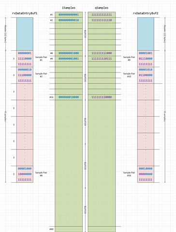
  2. I tried using two buffers to alternate data filling and printing, allowing the printing task to process one buffer while the other fills with new data. However, even with double buffering, the callback frequency still occasionally overwhelms the printing process.

Questions for the Community

  • Has anyone encountered a similar issue with continuous data reception and UART output on the CC1352R?
  • What techniques have you used to manage high-frequency callback events while still outputting data over UART without losing data?

Any advice on how to handle the synchronization between the callback and UART printing task would be much appreciated. Thank you


  • I am afraid that we cannot help you any more with this, other than what we have already done in the original post.

    Again, if you do the suggested exercise where you toggle a led evertime you get an RF callback, you will see what you receive one byte every 6.66 us (radio operating at 12.5 kbps)

    it is not a problem to transmit UART data at this rate, but now sure you will manage when taking into consideration the code overhead of handling the RF callback and preparing the UART buffers etc.

    I am sorry that we do not have the available resource to help you any further with code for this.

    Siri

  • Thanks, Siri,
    I got that and somehow my code is working but I have some questions about handling received data entries. Currently, I am using a fixed value NUMBER_OF_SAMPLE_PAIRS as in patch file for loop within my callback function to process IQ samples received by the RF core.

    for (i = index; i < (NUMBER_OF_SAMPLE_PAIRS + index); i++)
    {
    iSamples[i] = (((*(packetDataPointer + 1)) << 8) |
    (*packetDataPointer)) & 0x0FFF;
    qSamples[i] = (((*(packetDataPointer + 2)) << 8) |
    (*(packetDataPointer + 1))) >> 4;
    packetDataPointer += 3;
    }


    Fixed NUMBER_OF_SAMPLE_PAIRS with Unknown Data Length:

    • Right now, NUMBER_OF_SAMPLE_PAIRS is fixed, but I am not sure if that is the best approach since I don’t know the exact length of incoming data for each packet. if the actual number of samples received varies, how would I determine the actual sample count in each callback, and would I dynamically adjust NUMBER_OF_SAMPLE_PAIRS be a better approach?

    Setting Incoming Data Length in partialReadEntry1 and partialReadEntry2:

    • I am also wondering in patch example its setting the incoming data length in partialReadEntry1 and partialReadEntry2. How does this length setting work within currentReadEntry? Are the entries pre-configured to handle a maximum length, or is the length dynamically updated as data arrives?

    If anyone has insights on whether I need to make NUMBER_OF_SAMPLE_PAIRS dynamic due to the unknown length of incoming data, on best practices for setting up and using these partial entries, or on how currentReadEntry interacts with partialReadEntry1 and partialReadEntry2, I would really appreciate the guidance

  • I will try to explain how the different buffers work.

    First of all, the radio works in infinite mode, meaning that it will receiev IQ Samples until the application tells it to stop RX.

    To be able to know when you should exit RX, you will need to proccess the incoming IQ samples on the fly, to convert it into meaningful data yourself, to see if what you are receiving are just noise or if it is "real" data.

    We will not offer any support on how to process the data, as the recommended way to use the radio is to let the RF Core itself do all this for you and just provide you with the received data in a buffer.

    However, since you for some reason want to process the IQ samples yourself, I will explain how the buffers in the app note are used.

    The RF Core writes the IQ samples to rxDataEntryBuf1 and rxDataEntryBuf2.

    Each of these buffers have room for 8 sample pair, and each pair is 3 bytes (12 bits I sample, and 12 bits Q sample).

    You get an interrupt every time one of the rxDataEntryBufx buffers are full, and then you basically have to process these 8 samples while the radio continous to fill up the rxDataEntryBuf that you are not handling.

    There are two other buffers (iSamples and qSamples) that in my example holds 40 sample each (NUMBER_OF_SAMPLE_PAIRS*NUMBER_OF_BUFFERS).

    That means that the first time you get an interrupt (rxDataEntryBuf1 is full), you fill up the both iSamples and qSamples with the 8 first samples.

    When you get your next interrupt, you have sample 9 through 16 available in you rxDataEntryBuf2.

    Next you will get a 3rd interrupt (rxDataEntryBuf1 is full again), and you will have sample 17 - 24 availabe.

    After 5 interrupts, you have filled your iSample and qSample buffer, and on the 6th interrupt (rxDataEntryBuf2 full for the 3rd time), you start overwriting the 8 first entries in iSample and qSample buffers, so you need to be done with whatever you want to do with the 8 first samples (in your case, writing them over UART)

    Since you want to transmit the I and Q samples over uart, I assume that you are not proccessing the samples on the CC1352. Whatever device you use for processing the data, is responsible for signalling back to the CC1352 that it has received the samples that it needs and that RX can be exited.

    Siri

  • I understand that each rxDataEntryBuf can only store 8 sample pairs and that we receive an interrupt each time one of these buffers is filled. However, I noticed that the code is using NUMBER_OF_SAMPLE_PAIRS in the loop, like this:

    for (i = index; i < (NUMBER_OF_SAMPLE_PAIRS + index); i++)
    {
    }

    For instance, if I set NUMBER_OF_SAMPLE_PAIRS to 50 with 5 buffers, I would expect this setup to handle 250 samples after 5 interrupts. However, since each interrupt only provides 8 samples, the total received would be 40 samples, not 250.

    Could you clarify why NUMBER_OF_SAMPLE_PAIRS is used in the example app if each buffer only holds 8 pairs?

  • The reason I said that each buffer only holds 8 pairs is because the example set 

    #define NUMBER_OF_SAMPLE_PAIRS 8
    

    and the bufers that the rf core writes to only have room for 12 + 8*3  = 36 bytes.

    12 of them are the header, and there are 3 bytes per sample, hence 8 samples.

    rxDataEntryBuf1[PARTIAL_RX_ENTRY_HEADER_SIZE + (NUMBER_OF_SAMPLE_PAIRS * 3)]

    If you set NUMBER_OF_SAMPLE_PAIRS to 50, the buffers will have room for 12 + 50*3 = 162 bytes (50 samples of 3 bytes each), and you will not get an interrupt before the buffer is full.

    Siri